Altitude
advanced hybrid synthesis workstation
User Manual
Introduction
Congratulations on your purchase of the Altitude synthesizer!
Altitude is a modern musical instrument that combines subtractive, sampling and FM
synthesis, enabling you to produce a wide variety of complex sounds.
Booming basses, provocative pads, effervescent effects, sonorous sequences:
whatever your mix needs, it’ll only be a few clicks away.
And with a generous library of builtin patches, inspiration is inevitable.
The clear, responsive user interface serves as your guide through your auditory adventures.
With its straightforward layout, exploring the deepest depths of the audio engine’s facilities
is just as effortless as making your first patch.
The design is alive with visual aids and reactive displays that make it a
cinch to work on intricate patches, or get to grips with something you’ve just loaded in.
With four included skins, as well as a custom skin template,
it’s easy to adapt the synthesizer to fit your creative space.
The factory ROM comes bundled with a range of textural samples that can be layered and tweaked,
providing a quick way to fine-tune the timbre of your patches.
A multitude of high-quality filter algorithms are available from the two filters.
The Effects page features a selection of reorderable units,
their characters spanning from delightful and airy to dark and gritty.
The Sequence page sports two sequencer-arpeggiators, with an assortment of generative gadgets
and polyrhythmic possibilities.
Ample opportunities for modulation are included, with numerous envelopes,
multi-segment LFOs and Math modulators accessible from all pages of the interface.
We hope you enjoy using Altitude!
Installation
Windows
First, download and extract the .zip file for the Windows version of Altitude.
From the extracted folder, open the Installer.exe application.
If you are prompted by anti-virus software or Windows Defender, select Show more, Run anyway
or similar.
You will then be prompted to run the installer as an administrator.
With the installer open, read and agree to the end-user license agreement.
If you do not agree to terms of the license agreement, click Cancel
and then delete the installer.
On the next page, you can select which formats of Altitude you want to install.
For the plugin formats, the location they will be installed to is displayed.
Once you have made your selection, click Install and wait for the installation to finish.
Finally, restart your host application and rescan for new plugins.
To uninstall Altitude, open the installer again and instead of clicking Install,
choose Uninstall. All installed formats will be removed.
macOS
First, download and extract the .zip file for the macOS version of Altitude.
Go into the folder for the format you want to install.
Then, follow the instructions in the Instruction Guide.txt file.
You must close any host applications like Bitwig before installing.
To uninstall, simply delete the files you copied during installation.
If you also want to delete your user settings, you can find them in Library/Preferences/nakst.audio.ini.
Linux
First, download the .tar.gz file for the Linux version of Altitude.
Open a terminal emulator and set the current directory to the folder containing the .tar.gz file.
Then enter the command,
tar -xaf Altitude*.tar.gz && AltitudeLinux/install.sh
GUI controls
There are various controls throughout the graphical interface of Altitude.
This section describes how to recognise each control, and the methods of interacting with them.
Dials, sliders and steppers
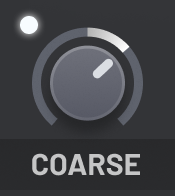


These controls represent a numerical parameter for the audio engine.
Left click and drag on the control to change the parameter’s value.
While dragging, move your cursor upwards to increase the value.
Move your cursor downwards to decrease the value.
While dragging, a popup will appear to display the exact value of the parameter.
Some parameters have important values.
While dragging, hold the Shift key to automatically snap the value to
these important values.
For example, the Coarse Pitch dials will snap to octaves.
The popup will indicate when snap points are available.
With your cursor hovering over one of these controls,
you can also scroll your Mouse Wheel to adjust the parameter value.
To reset the parameter to its initial value,
you can Middle Click on the control, or Double Left Click,
or hold Alt while left clicking.
When you Right Click on the control, a context menu will appear with additional commands.
Some of these commands will be provided by your host software.
Altitude provides commands for copying, pasting and resetting the value of the parameter,
and usually a command for entering the value numerically in text is also provided.
When a dial represents a parameter that is being modulated,
the outer ring of the dial will update automatically
to display the modulated value of the parameter,
rather than the base value.
XY pads

The XY pads let you control the values of two macro parameters at once.
They behave similar to Dials.
When dragging, move your cursor horizontally to affect one parameter,
and move your cursor vertically to affect the other.
Choice boxes

Choice boxes let you select a choice of a parameter’s value from a list of options.
Left click on the box to open the menu.
The choice box will display the currently selected option.
Modulation destination boxes appear similar to choice boxes,
however when clicked they do not open a menu.
Instead, they enter modulation destination selection mode.
In this mode, you can click any control that represents a parameter
to assign the modulation source to this parameter.
Other controls will be dimmed.
Some controls will still work as normal however,
such as the page and tab switcher controls.
If you want to exit modulation destination selection mode without making an assignment,
click anywhere on the interface that has been dimmed.
To remove an existing assignment,
enter modulation destination selection mode as usual,
and a button labelled ‘Remove assign’ will appear below the box.
Click this to remove the assignment.
Radio boxes

Radio boxes let you select one option from a choice of many.
In this way, they have a similar purpose to choice boxes.
However, with radio boxes, all the options are visible on the interface at once.
Click on the option you want to select it.
The previously selected option will automatically deselect itself.
Toggle boxes

Toggle boxes often appear in a similar style to radio boxes.
However, they have a different purpose.
Toggle boxes represent an on/off parameter.
Left click the box to enable the parameter, and click again to disable it.
Buttons

Buttons perform a specific action when you left click on them.
Typically, buttons are labelled with an indication of the action they will perform when clicked.
Buttons that open a popup or dialog box are labelled with trailing ellipsis.
Some buttons open menus, allowing you make a selection of which action you want to perform.
An important example of buttons is the collection of State buttons.
Many units on the interface have a State, usually in the top-right corner of their section.
Clicking on these buttons opens a menu, providing options to management the state of that particular unit.
You can copy the state of other units into the selected unit.
You can randomize the state of the selected unit.
Sometimes you can load standard presets for the unit (such as in the curve editors).
You can also save and load you own custom-made presets for the unit.
See the Settings for information about where these presets are stored.
Other important buttons include the Move and Delete buttons
in the top-right corner of every loaded effect unit.
The Move button lets you switch the unit’s position in the effect chain
with another unit.
The Delete button removes the unit from the chain so that you can replace it
with a different unit.
The parameters of the effect unit are not lost when you delete it;
add the effect unit back to restore the settings.
But note that there can be up to three instances of each effect type,
and each has different parameters.
Scroll bars
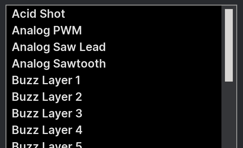
Scroll bars are used to allow you to view large lists of items that cannot
allow fit in the interface at once.
Left click and drag on the scroll bar’s thumb to move it.
When you move the bar up, the list contents moves down.
When you move the bar down, the list contents moves up.
The size of the scroll bar thumb is proportional to the fraction of the list’s items that are visible.
Left click above the thumb to move up by half the number of visible items.
Left click below the thumb to move down by half the number of visible items.
Macro label editor

Left click on the label below macro dials to open a text entry dialog prompt.
You can use this entry to select a new label for the macro.
Patch display

At the top-left of the interface is the patch display.
It displays the name of the currently loaded patch and the author.
Left click on the name of the patch to open the patch menu.
Please refer to the Patch management section of this manual for
further information about the patch menu.
Left click on the name of the author to change the stored name.
Do not forget to re-save the patch after updating the author, if needed!
Left click on the up and down arrows on the right side of the patch display
to load the previous and next patch respectively.
Sample box

On the right side of the sample layer units you will find a sample box.
It displays the name of the currently loaded sample.
Left click on the name of the sample to the open the sample picker dialog.
Please refer to the Sample management section of this manual for
further information about the sample picker dialog.
Drag and drop a supported sound file onto the sample box
to import it into the sample library and open it in the layer.
Please refer to the Sample management section of this manual for
further information about the sample importing process.
Left click on the left and right arrows on either side of the box
to load the previous and next sample in the category respectively.
Page switcher

At the top-right of the interface is the page switcher.
Left click on the page’s name to switch to it.
You can also right click on any area of the interface
to bring up a menu from where you select a page to switch to.
Tab switcher
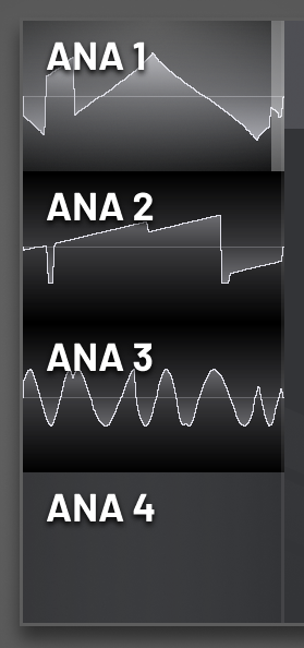
On the side of the generator and modulator units are tab switchers.
These let you switch to a different unit’s interface.
The highlighted segment of the switcher corresponds to the currently selected tab.
Left click a tab to switch to it.
For a generator tab, an oscilloscope preview of the generator’s output will be displayed
on the tab segment. If the generator is disabled, the segment will be grayed out.
For a modulator tab, an oscilloscope preview of the modulator’s control signal will be displayed
on the tab segment. If the modulator is not connected to any destinations, the segment will be grayed out.
For the generator tabs, right click to open a menu that lets you solo the generator.
The tab switchers for generators also have toggle boxes that let you quickly enable and disable
each generator. Shift left click on one of the toggle boxes to solo the generator.
Trancegate pattern

Left click to toggle a step in the pattern.
The left and right stereo channels will be toggled together if the Stereo
option is disabled in the trancegate unit.
Pattern delay pattern

Left click and drag to adjust the volume of one of the left channel taps in the pattern.
Right click and drag to adjust the volume of one of the right channel taps in the pattern.
The left and right stereo channels will be toggled together if the Stereo
option is disabled in the delay unit.
Octave multi-selection
In the keyboard mapping popup for the generators,
there is a control that lets you select which note octaves will be sent to that generator.
Left click on an octave to toggle it.
Left click and drag on a range of octaves to enable or disable them all.
Whether they will be enabled or disabled is determined as the opposite
of the state of the octave that the drag started on.
Step modulator pattern
Left click on one of the shape tools below the pattern editor to select it.
The active tool is highlighted with an outline.
Left click and drag on a step in the pattern to adjust its start value.
Right click and drag on a step in the pattern to adjust its end value.
When you first click on a step its shape will be updated to match the tool,
as long as shift is not held.
While dragging, hold shift to snap the value to twelfths. This is useful for aligning
the value to semitones in an octave.
Curve editor
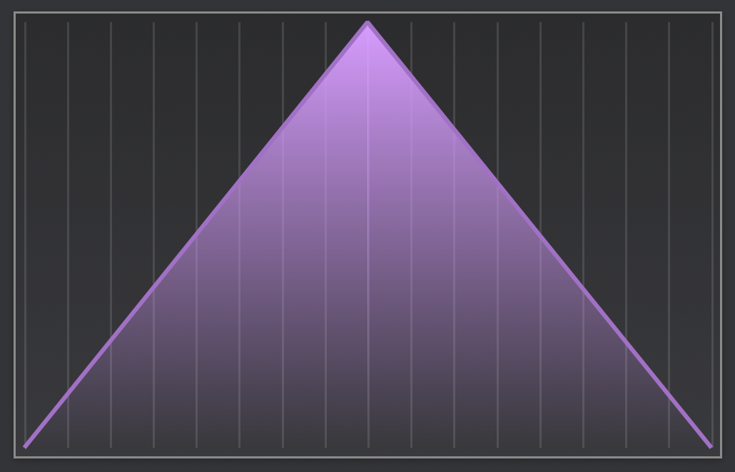
The curve editor is used to create a custom function.
The curve is made up of points.
Each point has a horizontal and vertical position.
Points are horizontally constrained between the previous and next points.
The connection between each pair of adjacent points has an associated tension,
which determines the acceleration of the curve between the points.
To view the handles for modifying the points and tensions,
hover your mouse cursor over the curve editor control.
Left click and drag on a handle to move it.
Tension handles can be moved vertically.
Point handles can be moved both vertically and horizontally.
Right click and drag on empty space to create a new point
and position it.
Right click on a tension handle to reset it to the default,
a straight line connection.
Right click on a point handle to open a menu
which allows you to copy and paste the vertical position of the point or
delete the point.
Note that you can only delete a point if there are more than two points in the curve.
A curve cannot have less than two points.
For the curves in the LFO units,
the point handle menu also lets you change the current loop start point.
If a point is the loop start point, it will be highlighted.
If the first point is selected as the loop start,
the curve will loop from the very beginning
(even if the first point is actually moved away from the left edge).
In this case, no point is highlighted.
Left click and drag on empty space to select a range of points.
Left click on empty space to deselect all points.
With some points selected, left click and drag on one of the point handles
to move all the points together, both vertically and horizontally.
Right click on one of the point handles to delete all the selected points.
Hold shift while dragging point handles to snap them to the grid.
Left click the Grid button next to the curve editor to adjust the grid spacing.
You can select the horizontal and vertical grid spacing.
You can also remove the grid on either axis.
Grid divisions can range from halves up to sixteenths.
Interface overview
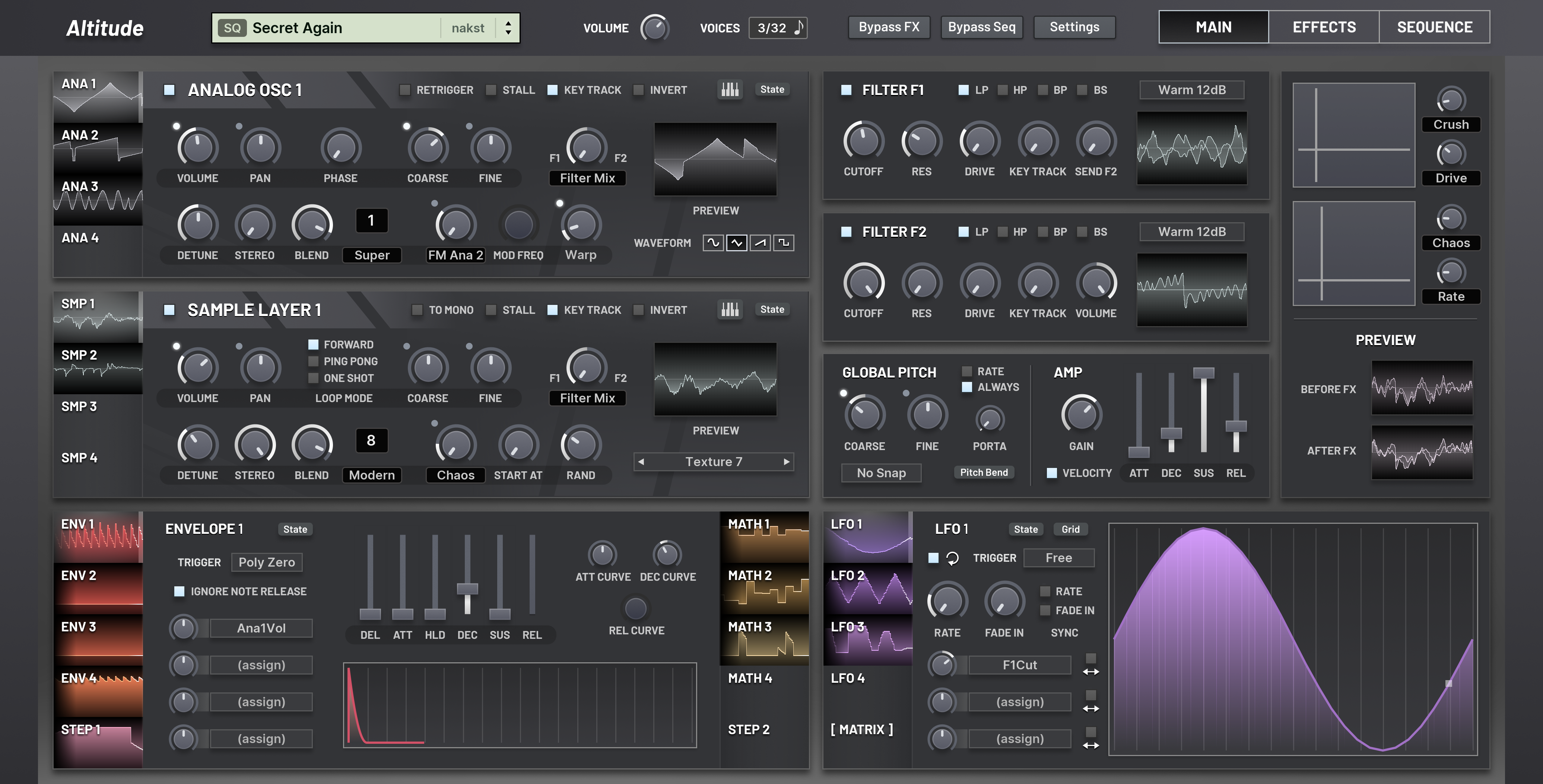
The interface is divided into three pages.
The top bar and modulation section (at the bottom) are visible on all pages.
You can switch the active page by using the page switcher on the right side of the top bar.
The first page is the Main page. It contains the generators on the left;
the filters, global pitch and amp settings in the middle; and the macro controls on the right.
The generators are divided into two groups: the virtual analog oscillators, and the sample layers.
You can switch between the four units of each using the tab switchers on the left of the groups.
Each generator and each filter has an enable button in the top left corner of the unit’s interface.
Click this to toggle whether the unit is enabled or bypassed.
The second page is the Effects page.
It contains eight slots into which one of the numerous effect units can be inserted.
The effect slots are grouped into two chains, A and B.
You can change the effect ordering from serial to parallel with the controls on the right.
The third page is the Sequence page.
It contains the controls for the two sequencers and their corresponding arppegiators.
Click the enable box in the top left corner of the respective sequencer to enable it.
Then adjust the sequencer length using the controls in the middle,
and then you can customise the sequence steps.
The modulation units are found at the bottom of the interface.
The units are in two groups.
The first group contains the envelope generators, the math modulators, and the step modulators.
The second group contains the LFOs and the modulation matrix.
You can use the tab switchers to select the visible unit in the group.
Each modulation unit has a list of assignments of its left side, and
each assignment slot has an attached amount dial.
The top bar contains various global controls.
The patch display is on the left side. Click this to open the patch menu to browse patches.
Then there are the master volume and polyphony controls.
Next are the bypass buttons, which allow you to bypass various sections of the sound engine.
Then is the settings button, which contains global settings for all instances of the plugin.
Finally on the right hand side is the page switcher.
Patch management
Altitude comes with over 300 builtin patches in its factory ROM.
You can also save, export and import user-made patches.
User patches are stored in a dedicated folder you chose when you first launched Altitude.
You can change this folder by selecting Change user content folders from the Settings menu.
In the top left corner of the interface is the patch display.
It displays the name and author of the currently loaded patch.
If you are making your own patch, you can left click the author segment to change it.
On the right side of the patch display are two arrows which let you quickly
go to the previous and next patch from the full list of patches.
You can left click on the patch name segment to open the full patch menu.
Patch menu
The patch menu lets you manage your patches as well as load existing ones.
Simply click on a patch in the menu to load it.
The patches in the user patches folder are appended at the bottom of the menu.
Each folder is represented by a submenu.
Save patch…
Save the current state of the synthesizer’s parameters to a patch file.
The save dialog will default to your user patches folder.
Make sure you do indeed save to this folder,
otherwise Altitude will not be able to find the file later.
Initialise patch
Reset the state of all the synthesizer’s parameter to their default.
You can customise the init patch from the options in the Settings menu.
See the corresponding section of the manual for more details.
Recent patches
Everytime you load a patch, initialise the parameters, or perform a randomisation action,
the previous state of the synthesizer will be saved to temporary storage,
and will be made accessible in this menu.
It is particularly useful if, for example, you accidentally initialise a patch
instead of saving it.
The 10 most recent states will be stored in this menu.
Show patches folder
Open the user patches folder in your default file browser.
From here, you can rename and sort your patches.
You don’t need to rescan for changes in Altitude after you do this;
it will automatically pick up any changes.
Patches in the factory ROM are not kept in this folder; they are stored internally.
Import bank…
Import all the patches in a bank file into your user patches folder.
This action will also import all the samples from the bank file
that you don’t already have in your sample library.
See the section on Sample management for more information
about how the sample library is automatically managed.
Export as sample…
Renders the current patch to a sample and start importing it.
See the next subsection for details on the controls in the export screen.
Randomize patch
Randomize all parameters.
If you just want to randomize the parameters of a particular unit,
look for a State button on that unit’s interface section.
Evolve patch
Randomize all parameters,
but try to keep most parameters close to their previous values.
This causes the patch to ‘evolve’ without changing completely.
Blend patch…
Mix the values of each parameter with those from another patch,
blending their characters together.
Export as bank…
This option is only shown in the submenus for user patches.
Export all the patches in the folder to a bank file.
Any samples used by the patches will also be saved to the bank file,
so that they can be imported with the Import bank… command.
Export as sample
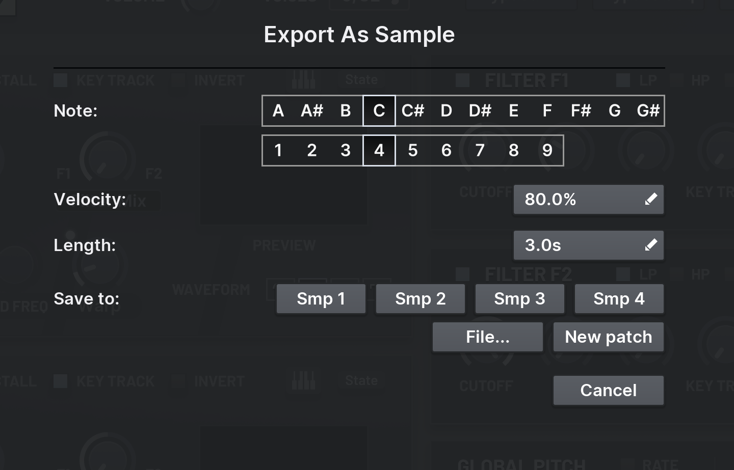
The Export as sample… command in the patch menu lets you export the current patch
as a sample, and save it either to a file or immediately load it into one of the sample layers.
In the export screen, you can modify various parameter about what will be rendered.
First, select the octave and note that will be played.
Then, select the velocity of the note and the duration of the rendered sampled.
Finally, select the export destination.
The Smp – options will begin the sample import process, and when it is complete,
the selected sample layer will be assigned to the new sample.
The File option saves the sample to a standard wav file.
The New patch option initialises the patch after rendering is complete,
and begins the sample import process into the first sample layer.
Sample management
Altitude includes a wide selection of samples that can be loaded into the four sample layers.
It also allows you to import your own samples into the sample library.
Altitude automatically manages the imported samples to ensure that
patches will be able to quickly and accurately find the samples they use.
Overview
Imported samples are kept in a customisable location.
To change where they are stored, click the Settings button in the top-right corner of the interface
and select Change user content folders. In the popup, click the Browse button
corresponding to the imported samples location. When you are done, click Confirm to exit the popup.
After changing this location, you will need to manually copy the contents of the old folder into the new one
to keep your old imported samples.
Imported samples are stored in a custom format which can be accessed by Altitude
and other of nakst’s audio plugins.
In fact, you can even have multiple plugins sharing the same sample library folder,
and they will seemlessly coexist, will the same selection of user samples available to all plugins.
Once a sample is imported, it will be given a special name that uniquely identifies it.
This has several benefits.
First, it prevents samples from being accidentally overwritten.
Second, it prevents a sample being duplicated in the library, wasting drive space.
And finally, it makes sure that the audio engine will be able to instantly match samples
to a patch that uses them, regardless of the sample’s display name in the picker.
You must not manually rename imported samples on your drive.
The user sample folder also contains an index file. Do not delete this:
it contains required information about the samples that have been imported into the library.
You should not manually modify this file.
If you are backing up your imported samples, make sure to include this file in your backup.
The sample importing system was designed specifically for the long-term reliability of your projects.
Even if samples are deleted from the library and re-imported at a later date with a different name,
your old projects will still be able to find the original sample, and they will never mistake
a different sample for the one they require.
Picking samples
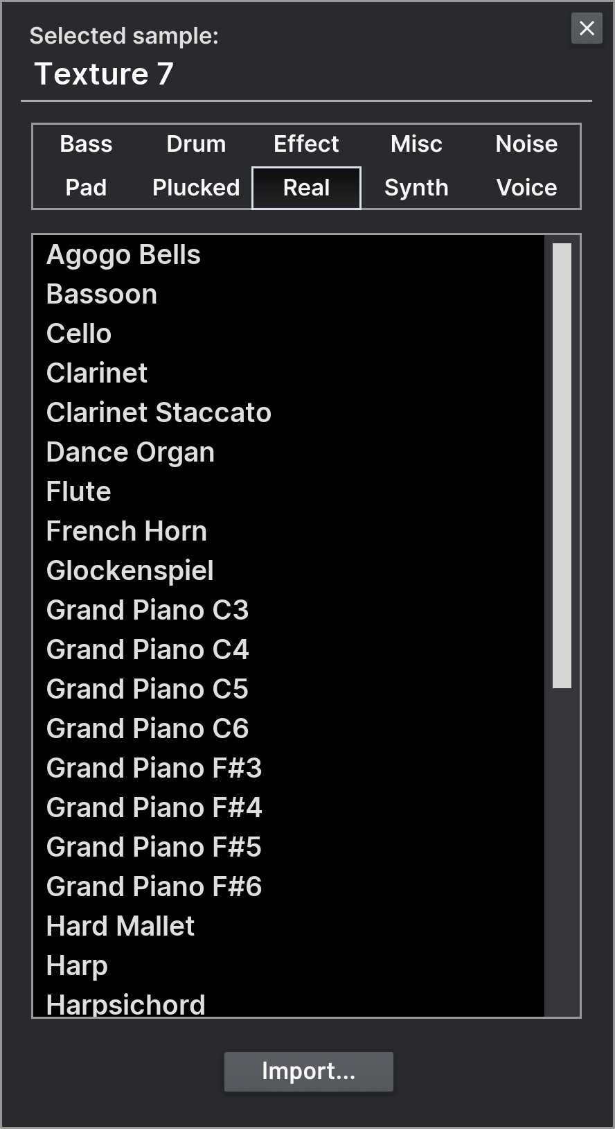
To change the loaded sample for a sample layer, click the sample box in its lower-right corner.
This will open the sample picker popup.
Click anywhere outside the popup to close it when you’ve selected the sample.
Alternatively to switch samples, you can click the left and right arrow buttons on either side of the sample box.
These buttons cycle through the samples in the current sample category.
At the top of the sample picker popup are the ten sample categories.
Left click on the name of a category to view the samples inside it.
The sample list below will then be populated with these samples, sorted alphabetically.
Left click on a sample to select it. The selected sample will be highlighted.
Right click on a sample to view more commands for that sample.
Currently, the only extra command is the option to remove a sample from the library.
You can only remove user imported samples; the samples included the factory ROM cannot be removed.
Important: Because sample data is stored externally and not as part of saved patches
or projects, deleting samples will break any patches or projects that use them.
Importing samples
From the sample picker popup, click the Import… button to begin importing a sample.
Select the wave file you want to import. Only standard format, uncompressed ‘.wav’ file are supported.
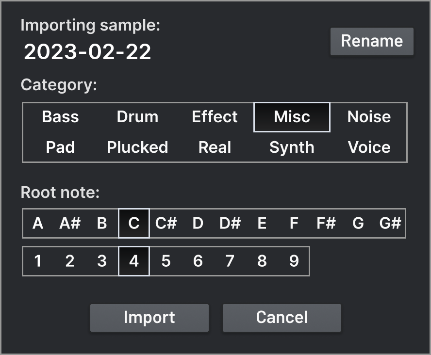
After the file has been selected, you will be shown the sample import popup.
Here, you can rename the sample before it is imported,
select the category it will be imported into,
and select the root octave and note of the sample.
It is important to enter this information correctly; if you get it wrong,
you will need to remove the sample and re-import it.
On the sample import popup, you will be able to preview the sample before it is actually imported.
Make sure that the selected sample layer is enabled before beginning the process.
The sample being imported will be used by the sample layer when you play notes.
Click the Import button to finish importing.
If you are sharing the user samples folder with other plugins,
you will need to re-open them before they will find the newly imported sample.
Settings
Click on the Settings button at the top of the interface to open the settings menu.
Audio and MIDI
This option is only available in the standalone version of the synthesizer.
Select your audio output device and MIDI input device.
You can change the buffer size for audio output;
decreasing the buffer will decrease latency (making the synthesizer more responsive to input notes)
but increase the probability of glitches in the audio if the CPU is overloaded.
Some platforms will allow you to change the sample rate,
but you are recommended to use the default for the device,
as it will not require any rate conversions,
which could increase latency and decrease audio quality.
Scale
Select the scale of the interface, so that it takes up the right amount of space on your monitor.
If Altitude is able to detect the size of your monitor,
sizes that would not fit are automatically hidden.
Skin
Select the visual appearance of the interface.
You can also select a custom skin: choose a folder containing the custom image files.
A template is provided for the custom skin on the download page.
You can modify any of the images in the template to adjust how that component
of the interface will appear.
The palette.ini contains a list of colors used by the interface
using hexadecimal color codes.
You can modify these to adjust how text and diagrams appear, since these parts do not use image files.
Refresh
Determines how quickly the preview displays on the interface are updated.
If you have an older CPU, you may want to select Slow UI refresh
so that more CPU time can be dedicated for processing audio,
rather than updating the interface.
Dial smoothing
If this option is enabled,
the values of dials will be smoothed as you drag them in the interface,
preventing digital clicks as the parameter changes.
(This is not applied to parameter automation from the host.)
Show LFO phase indicator
If this option is enabled,
the LFO curves will display a dot indicating where in the cycle
the LFO currently is.
Change user content folders
This option opens the popup that allows you to change
where patches, samples and unit presets are stored and loaded from.
This popup was shown when you first opened Altitude.
Init to default
When you load the plugin, or when you initialise the patch,
the default init patch will be loaded:
an unfiltered sawtooth with a ping-pong delay effect.
Init to empty patch
When you load the plugin, or when you initialise the patch,
a completely empty patch will be loaded.
Custom init patch
When you load the plugin, or when you initialise the patch,
the selected patch will be loaded.
If the selected patch is later moved or deleted,
the default init patch will be used instead.
About
Shows the about popup, including the credits.
Click anywhere on the popup to dismiss it.
User manual
Navigates to the user manual in your web browser.
Visit website
Navigates to Altitude’s website in your web browser.
Signal flow
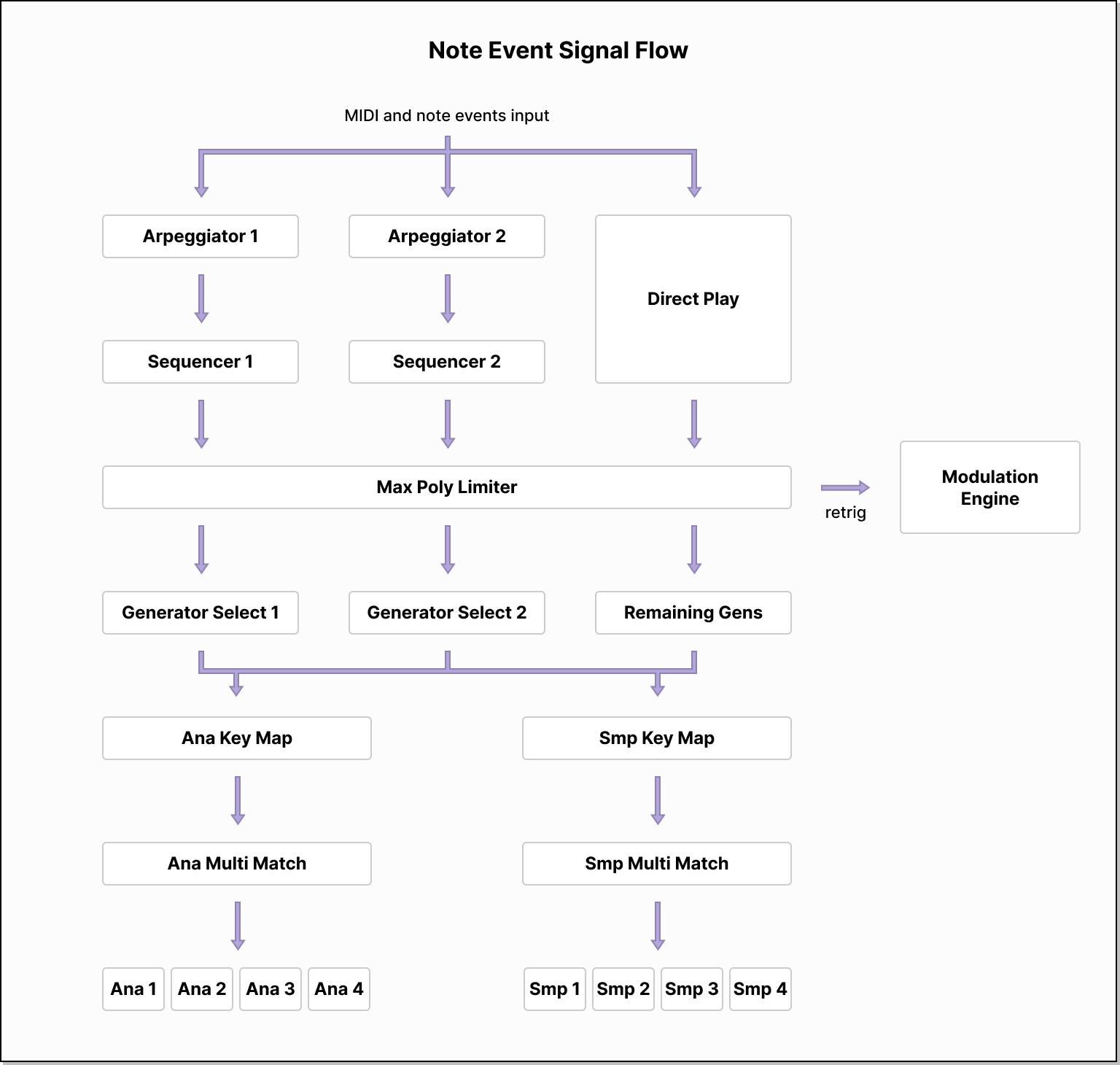
The signal path begins with the receival of note events from the host.
This may be in the form of MIDI messages, or by some other plugin format specific means.
When a note on event is received, the following logic is taken.
All enabled sequencers have their new note flag set,
so that on their next step they can retrigger modulation units with the Mono Last trigger mode.
If monophonic mode is disabled or are no notes already playing,
AND there are generators not assigned to any (enabled) sequencer,
then a new voice is spawned.
When a note off event is received, the following logic is taken.
For the arpeggiators running in As Played mode,
if this note was their last played note, then they restart their enumeration of the notes.
If monophonic mode is disabled, then all voices not spawned by a sequencer begin releasing.
If no notes are now on, the sequencers are reset and any voices spawned by them begin releasing.
After the initial processing of a note on or off event, the following logic is taken
when monophonic mode is active.
If there is still a non-zero numbers of notes that are on, then
the engine searches for the note that is still on and was most recently played.
If this is different to the currently active voice, then
the voice is reassigned to that note, including the updating of its pitch and resetting of the portamento timer.
If a note is switched with legato disabled, the modulation units will be retriggered.
Then, if the event was a note off event and the active voice still corresponds to this note,
(i.e. no other note could be reassigned to it), then the voice begin releasing.
Once note events have been processed,
the engine begin releasing voices from disabled sources.
For example, this prevents voices from becoming stuck when you disable a sequencer.
Next, all enabled sequencers are updated.
If there are no notes that are on, then the sequencer does nothing.
The sequencer first updates the step indices of each of its rows and toggles the swing phase.
If the sequencer has passed the gate for the current step, then any voices it has spawned begin releasing.
If the sequencer has passed the end of a step, then it will either trigger a new voice
or, if legato is enabled and the previous step had 100% gate length, it will change the pitch of the existing voice.
If the gate length is zero for a step or its random probability dice roll fails, then no voice is triggered.
When the arpeggiator steps, it selects a new note using the algorithm for its current mode.
See the section on the Sequencer for more information.
Next, the MIDI pitch bend wheel is smoothed, dials are smoothed, and the modulation units are processed.
The engine is now ready to generate sample data for each voice.
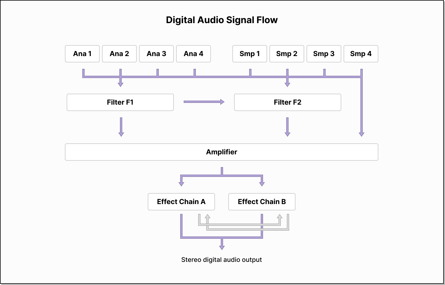
First, each enabled generator is processed, and their output is sent to
Filter F1, Filter F2 and the amplifier, depending on their settings.
Unless it is bypassed, Filter F1 applies its filtering algorithm to input.
Some of the output of Filter F1 is then set to Filter F2, depending on the Send F2 parameter.
This happens regardless of whether either filter is bypassed.
The rest of the signal is sent to the amplifier.
Unless it is bypassed, Filter F2 then applies its filtering algorithm to input,
and multiplies it by the Volume parameter.
The output of Filter F2 is sent to the amplifier.
At the amplifier, the amp envelope and gain are applied, and then voices are mixed down to a single signal.
Global modulation data is generated, and the signal is sent to the effect units.
Assuming the effects have not be bypassed with the Bypass FX button,
the signal is sent through the units in an order determined by the selected effect ordering.
See the section on effects for more information.
Once the effects have been applied, finally the master volume is applied to the signal,
and the audio data is returned to the host.
Generators
The eight generator units are found on the left side of the Main page.
The four virtual analog oscillators are grouped together, and the four sample layers are similarly grouped below.
Each group of four generators has a tab switcher on its left side.
You can switch to the editing interface of a particular generator by clicking on its tab.
You can enable and disable generators using the toggle boxes that appear when hovering over the tab switcher.
Hold the Shift key while clicking a toggle box to solo the generator.
When a generator is enabled, its tab displays an oscilloscope preview of the unit’s output.
There are several parameters and controls that all generators have.
Enable
Determines whether the generation will output any sound.
Disable generators do not take part in layer matching for the keyboard map.
For example, if Ana 1/2 are enabled and Ana 3/4 are disabled,
all oscillators are mapped to the full keyboard range,
and the Round Robin mapping mode is selected,
then Ana 1 will be used for the first note,
then Ana 2, and then it will repeat back to Ana 1.
Volume
Determines the amplitude or loudness of the sound output by the generator.
At 0%, the generator is silent. At 100%, the generator is the loudest it can be.
At 50%, the level is −12dB, roughly a quarter of the maximum loudness.
At 70%, the level is −6dB, roughly half of the maximum loudness.
Pan
Determines the relative amplitude of the left and right stereo channels of the generator’s output.
At −100%, the sound is only output on the left channel.
At 100%, the sound is only output on the right channel.
At 0%, the sound is output to both in equal proportions.
A circular panning law is used, so that the overall energy is roughly maintained as the parameter is changed.
Coarse
The generator’s coarse pitch.
If Key Track is enabled, this parameter is relative to the pitch of the played note.
Otherwise, it is relative to middle C.
The dial automatically snaps to semitones.
If you hold Shift while dragging the dial, it will snap to octaves instead.
If the parameter is modulated, there is no snapping after modulation.
Automation from the host will be snapped to semitones, however.
If you need finer granularity, use the Fine parameter.
Fine
The generator’s fine tuning.
This is measured in cents.
100 cents corresponds to 1 semitone.
This parameter ranges from negative 50 cents (half a semitone)
to positive 50 cents.
If you need a greater pitch range, use the Coarse parameter.
Filter Mix
This parameter determines to where the output of the generator is routed.
If you select To Amp from the choice box below the dial,
then the output is sent directly to the amplifier section, skipping the filters.
With Filter Mix selected, use this dial to continuously determine how much
of the output is sent to Filter F1 and Filter F2.
In the middle, the output is sent to both filters in equal amounts.
Stall
When disabled, the phase or position of the generator is incremented
with each sample at a rate determined by the pitch of the generator.
When enabled, Stall prevents the phase/position of the generator from advancing.
This gives a static DC offset.
However, combined with phase modulation, the generator will produce phase distortion sounds.
This can be achieved by setting the generator’s FM source to one of FM Ana 1–4 or
FM Smp 1–4 and increasing the FM amount.
Some FM sources will not work because they are not implemented as phase modulation but
rather actual frequency modulation, such as the Chaos source.
Key Track
When enabled, the generator will follow the pitch of the played note.
When disabled, the generator’s pitch will be entirely determined by the various pitch settings.
Invert
When enabled, the polarity of the generator’s output is inverted.
This is useful for creating phasing effects with other generators.
For example, set Ana 1 to be an inverted sawtooth and Ana 2 a non-inverted sawtooth.
Then, detune the oscillators slightly using the Fine parameter.
This will emulate pulse-width modulation as the oscillators go in and out of phase.
Uni Detune
Determines how far apart the pitches of the unison voices are spread around the base.
This multiplies the detuning ratios that are provided by the unison mode.
The Super unison mode uses an irregular detuning pattern to create a rich, evolving sound.
The Hyper unison mode uses a regular pattern to create a sharp, beating sound.
The Modern unison mode uses a mix of both to create a very wide effect.
Uni Stereo
Determines the stereo spread of the unison voices.
For the Super and Hyper unison modes,
if the number of voices is even then half the voices will be panned to the left and half to right,
and if the number of voices is odd then one voice will be centered and the remaining split as in the even case.
For the Modern unison mode, the voices are spread across the stereo image evenly.
Uni Blend
Determines how much the detuned unison voices are mixed in with
the base voice (that is not detuned).
At 90%, all voices have the same amplitude.
Increasing past this point, the base voice will be decreased in amplitude while the
detuned voices remain constant.
Uni Voices
Determines the number of unison voices.
As the number of voices increases, the volume of the generator is automatically
decreased to compensate.
With the Super mode, there can be up to 7 voices.
With the Hyper mode, there can be up to 9 voices.
With the Modern mode, there can be up to 16 voices.
Uni Mode
There are three unison modes, Super, Hyper and Modern.
Each determines how the Detune, Stereo and Voices
parameters behave.
You are encouraged to select the right mode for your patch by ear!
FM Source
Determines the source of the frequency modulation or phase modulation.
Some modes are only available for the virtual analog oscillators.
The FM Ana 1–4 and FM Smp 1–4 sources provide
phase modulation using the output of another generator.
Wobble uses phase modulation to simulate an oscillator
quickly going in and out of tune.
Drift is similar to Wobble, except it runs at much slower
rate, to emulate oscillator drift from old analog hardware.
Chaos uses frequency modulation to set the pitch of the generator
to a random multiple of the base frequency at every sample.
The LFO use frequency modulation to apply a LFO effect to the generator’s pitch.
There are four LFO shapes available, Sine, Triangle, Sawtooth and Square.
These modes are not available on the sample layers.
Notably, the Chaos and LFO modes are applied to each unison voice individually.
The LFOs will have a different, random phase offset for each voice.
And the Chaos generator will use a different random seed for each voice.
FM Amount
Determines the amount of frequency modulation or phase modulation.
Be careful when creating a feedback loop with the generators; increasing
the amount too high will produce loud feedback noise.
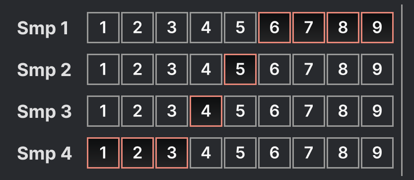
Keyboard mapping ranges
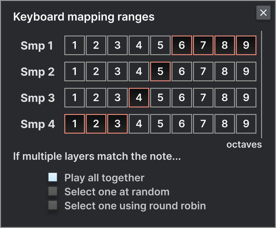
Clicking on the keyboard button in the top right of a generator will open the
keyboard mapping ranges popup for that group of generators.
For each of the four generators in the group, you can select
from which octaves each generator will respond to.
This is done at the input note level, so the Global Coarse Pitch
and Portamento do not affect in which octave a note is considered to be.
This filtering of octaves is done in addition to the generator filtering of the sequencers.
Make sure that if you send a sequencer to a generator that the output of the sequencer
is in the correct octave range for the generator to respond to it!
Additionally, you can select how the generator group responds when multiple generators
are matched for a given note. The default behaviour, Play all together
will play all the generators that match the note at the same time.
When Select one at random is active,
each time a new note is played, exactly one of the generators that matches its octave
will be selected, and only that generator in the group will output sound for the note.
When Select one using round robin active,
each time a new note is played, the next generator in sequence will output sound for the note.
So if all four generators match all octaves, then each time a new note is played,
the generators will activate in the order 1, 2, 3, 4, 1, 2, and so on.
Virtual analog oscillators
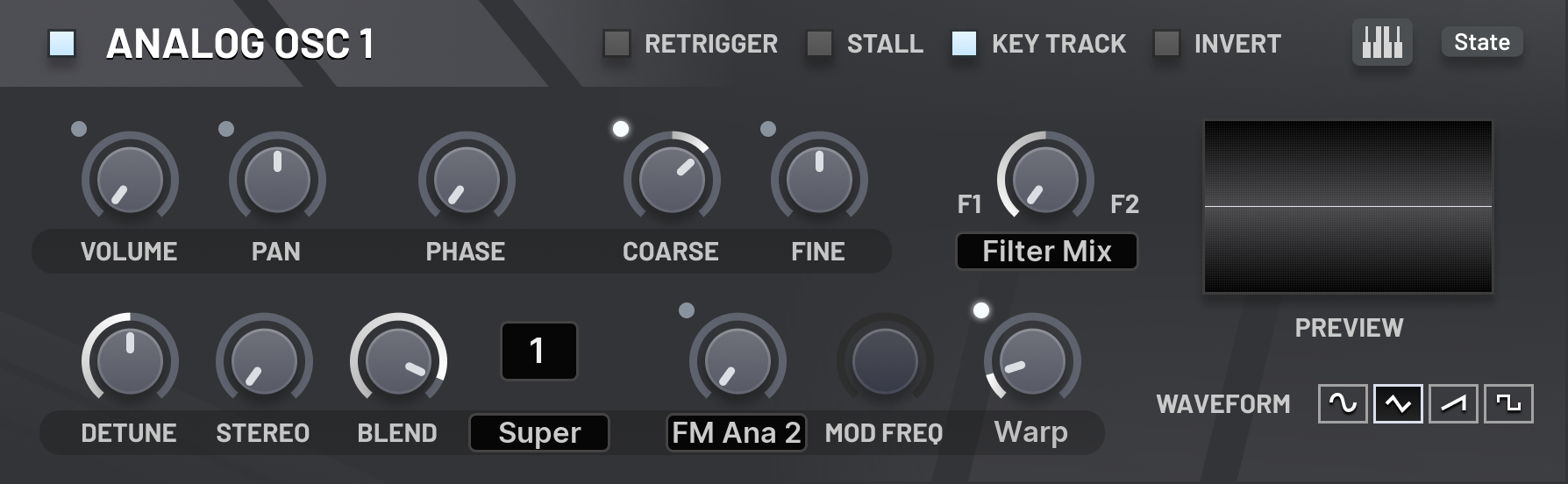
The four virtual analog oscillators provide a small yet versatile selection of classic subtractive waveforms,
each with a unique continuously controllable parameter to shape the sound.
Retrigger
When enabled, the phase of the oscillator will be randomised at the start of each note.
If disabled, oscillators start at zero phase.
Note that the Phase parameter is added to the oscillator’s phase
regardless of the Retrigger value.
Phase
An offset that is added to the current phase of the oscillator.
Notably, if Retrigger is disabled, then this will be the starting phase of the oscillator.
This parameter can be modulated to provide rudimentary phase modulation effects;
however, it is easier to use the FM Source and FM Amount parameters to achieve this.
Mod Frequency
When one of the LFO frequency modulation sources is selected, this parameter is available.
It will determine the frequency at which the LFO oscillates, which in turn modulates the oscillator’s frequency.
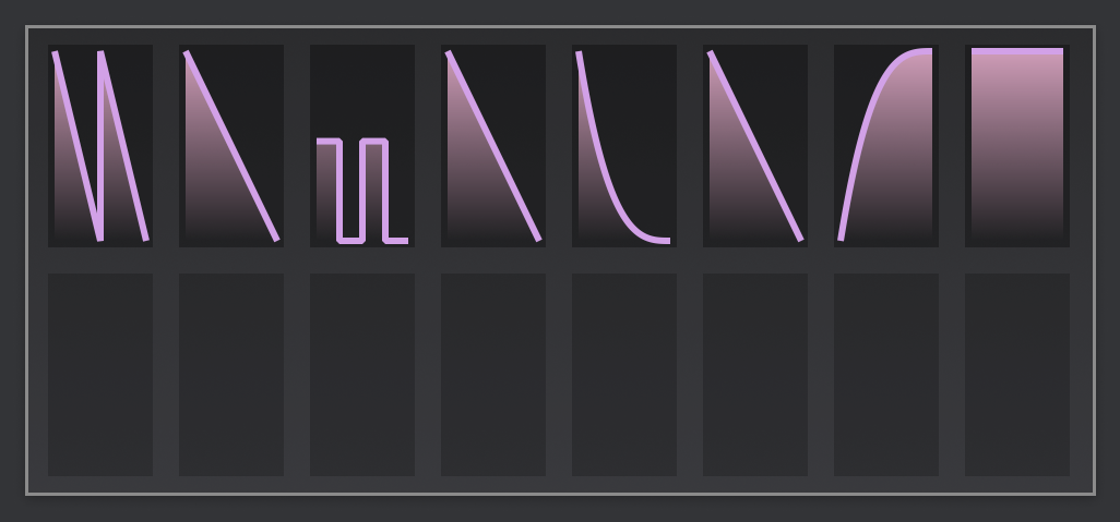
Wave Param
The parameter for the waveform depends on which waveform is selected.
For Sine, this controls the intensity of the ‘R-sync’.
The amount morphs the input phase to oscillator from a linear function to a rational function.
For Triangle, this morphs the original triangle waveform into a cubed triangle.
This makes a sharper waveform with more harmonics.
For Sawtooth, this introduces pseudo-pulses at an octave higher, and controls their widths together.
At 100%, the waveform is silent. At values 5%-15%, it produces a somewhat cheesy sound.
For Square, this controls the width of the pulse, or equivalently its duty cycle.
At 100%, the waveform is silent.
The pulse width effect is produced by summing two sawtooths of opposite polarity
and adjusting their relative phase.
In this way, adjusting the pulse width is not dissimilar from adjusting the time of a comb filter
with negative feedback.
Waveform
There are four waveforms available.
Sine is an approximation of a sine wave, a pure tone.
This approximation introduces a few additional harmonics,
to increase the character of the sound.
Triangle is a traditional triangle wave,
which adds a few odd harmonics, to produce a sound somewhere in between bright and dull.
Sawtooth is a bright waveform where all harmonics are including,
with amplitudes taken from the harmonic series.
That is, the harmonic of frequency nx where x is the frequency of the voice
has amplitude n−1.
Square is another bright waveform similar to the sawtooth, except it only has the odd harmonics.
Sample layers
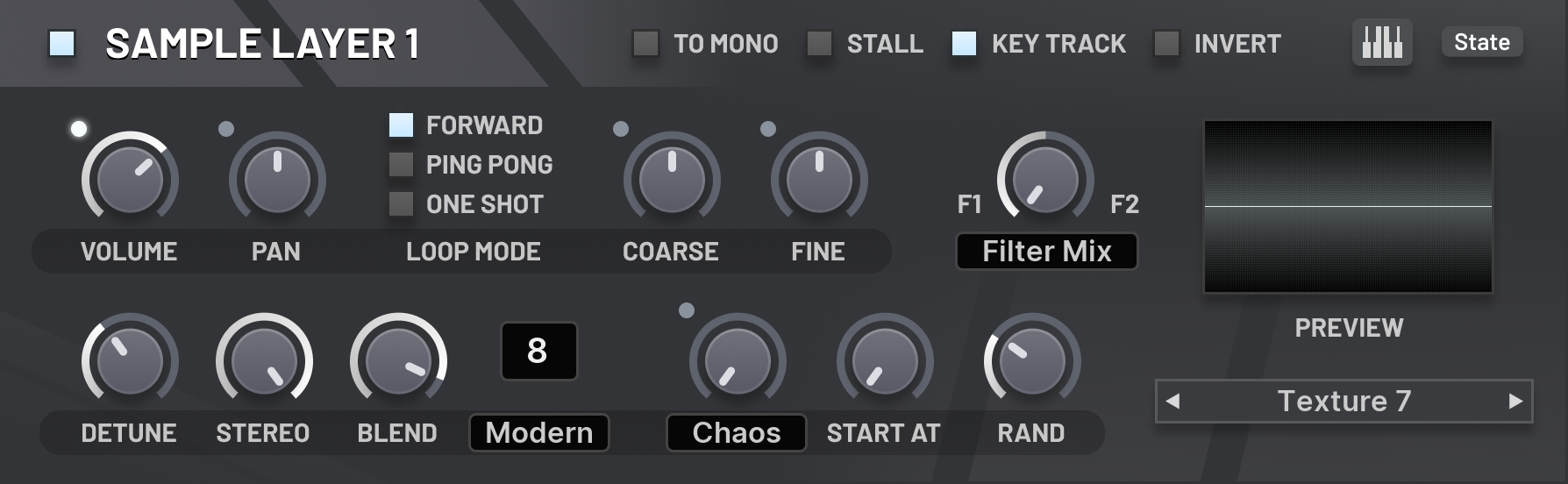
The four sample layers allow playback of a single sample each.
Using keyboard mapping ranges and layering strategies,
you can restrict which range of the keyboard each plays in,
or you can set the samples to play one at a time,
either chosen randomly with each note, or in a round-robin fashion.
To Mono
When enabled, the sample will be mixed down to mono before it is played.
Loop Mode
The loop mode determines what happens after the sample has been played once.
If Forward is selected, then the playback position will either
go back to the start of the sample, or if the sample has an embedded loop marker
then it will go to that point.
If Ping Pong is selected, then the playback will reverse direction
and play until either reaches a loop marker or the start of the sample,
at which point it will then return to playing in the forwards direction.
When it reaches the end of the sample again, the process repeats.
If One Shot is selected, then the playback will stop
once the end of the sample is reached, and the generator’s output will be silenced.
Start At
This determines the first possible position in the sample
that playback can begin.
The parameter is given as a percentage of the sample length.
If Start Rand is set to 0%, then
the selected point here will always be the starting position for playback.
Start Rand
This determines the size of the range of possible positions in the sample
that playback can begin.
The parameter is given as a percentage of the space in the sample after
the chosen Start At position.
When a voice starts, a random position in the sample is chosen from this range.
Each unison voice will generate a different random position.
This is useful if you don’t want the unison voices to have a flanging effect at the start,
similar to disabling Retrigger on the oscillators.
Global parameters

Master Volume
This dial is found on the top bar of the interface on all pages.
Determines the master volume of the plugin’s output, applied after all filters and effects.
Max Voice Count
This parameter can be adjusted by clicking the voice count
display on the top bar of the interface on all pages.
Determines the maximum number of voices that can be played at once.
If a new voice is spawned but the voice count has already reached the maximum,
the least recently played voice is immediately stopped.
The monophonic and monophonic legato modes have special behaviours
as detailed in the Signal flow section. But to summarise,
whenever at least one note is held, there will be one voice playing
with the pitch of the most recently played note that is held.
And when the pitch of the playing voice is changed
due to the most recently played held note changing,
all modulation units will be retriggered,
except when the legato mode is selected.
Bypass FX
This button is found on the top bar of the interface on all pages.
Bypass all the effect units.
The output of the amplifier is sent directly to the master volume control for processing.
Right click on this button to get access to the Lock option.
When Bypass FX is locked, it will be enabled,
and it will remain enabled as you load new patches,
even if the loaded patch did not have the Bypass FX parameter enabled.
To remove the lock, click on the button again.
Bypass Seq
This button is found on the top bar of the interface on all pages.
Bypass the sequencers. T
The sound engine will behave as if both the sequencers were disabled.
Right click on this button to get access to the Lock option.
When Bypass Seq is locked, it will be enabled,
and it will remain enabled as you load new patches,
even if the loaded patch did not have the Bypass FX parameter enabled.
To remove the lock, click on the button again.
Amplifier
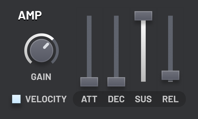
The amplifier unit’s interface can be found in the middle of the main page.
In the signal path, the amplifier is placed after the filters, and just before the signal is mixed to mono
from where it is sent to the effects.
Velocity to Amp
If enabled, the velocity of each note will be used to determine the peak amplitude
reached in the amplitude envelope. When disabled, a fixed peak will be used.
If you want to customise the velocity curve, disable this parameter,
and assign a math modulator (with the velocity source) to the amplifier gain parameter.
You can then adjust the curve using the remapping curve of the math modulator.
Important: In the FL Studio native version of the plugin,
the Channel Volume is used to determine the velocity of notes,
rather than the output volume of the generator.
Therefore, disabling Velocity to Amp may cause the Channel Volume to not work.
Gain
The final gain applied to the signal before the voices are mixed down to mono.
Attack
Determines the time between the start of the attack stage and the start of the decay stage.
During the attack stage, the amplifier gain starts at zero and moves up to the maximum.
The attack stage begins when the voice is spawned.
Decay
Determines the time between the start of the decay stage and the start of the sustain stage.
During the decay stage, the modulation value starts at the maximum and moves down to the Sustain level.
Sustain
Determines the value output during the sustain stage, as a fraction of the maximum level.
In this stage, the value remains constant.
The sustain stage is not left until the note starts releasing.
Release
Determines the time between the start of the release stage and the end point.
During the release stage, the amplifier level starts at whatever it was
when the release stage was entered and then moves down to zero.
Once the end point is reached, the voice will be removed.
Global pitch
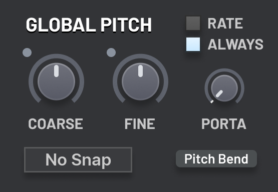
The global pitch settings can be found in the middle of the main page,
to the right of the amplifier.
The portamento control and pitch bend affect key tracking modulation;
the global coarse and fine do not.
Coarse
The global coarse pitch.
This is applied to all generators.
Before modulation is applied, the parameter value is snapped to semitones.
After modulation is applied, the parameter value may be snapped again,
depending on the selected snapping mode.
Coarse Snap
Controls the snapping that is applied to the global coarse pitch
after modulation is applied.
It can be snapped to semitones or octaves, or you can disable snapping.
Note that before modulation is applied the coarse pitch
parameter is always snapped to semitones.
Fine
The global fine tuning.
This is applied to all generators.
It ranges from negative half a semitone to positive half a semitone.
Porta Time
Determines the time it takes when a new note is played
for its pitch to slide from the pitch of the previous note.
If this time is set to zero, then no sliding will occur when a new note is played.
Porta Always
If enabled, the portamento sliding will always occur.
If disabled, the sliding will only occur if the new note begins
while the previous note is still held.
Porta Rate
If disabled, the portamento amount is given in units of time.
This time gives how long the slide takes.
If enabled, the portamento amount is given in units of octaves per second.
The length of the slide will then be proportional to how far apart the notes were played.
The further apart the notes, the longer the slide will take.
Pitch Bend
Determines the range of the pitch bend wheel in semitones up and down.
Important: In the FL Studio native version of the plugin,
this parameter cannot be changed in the plugin’s interface. Instead,
it is controlled in FL Studio’s interface.
Filters
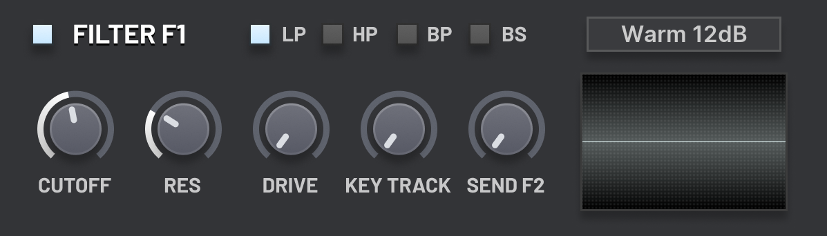
The two filter units are found on the right side of the Main page.
There are numerous filter algorithms available from the choice box in the top right corner of the units.
Many of these filter algorithms have a small selection of modes, selected using the toggle boxes on the top of the units.
You can bypass the filters using the toggle box in the top left corner of the units.
When a filter is bypassed, all of its inputs will be sent directly to the amplifier unit.
Filter algorithms
We give a description of the filter algorithms, and where applicable, their modes:
Light 6dB
A simple one-pole filter with two modes, low pass and high pass, and a gentle cutoff.
In the LP mode, frequencies below the cutoff point have unchanged amplitude.
In the HP mode, frequencies above the cutoff point have unchanged amplitude.
At the cutoff point, frequencies have a −3dB amplitude change.
On the opposite side of the cutoff point, frequencies have a decreasing amplitude applied,
at a rate of an additional −6dB every octave.
A −6dB change roughly corresponds to halving the volume.
Warm 12dB
A warming state-variable two-pole filter with four modes,
low pass, high pass, band pass and band stop.
The LP and HP modes behave similarly to the Light 6dB filter,
except the volume slope past the cutoff point is −12dB per octave.
In the BP mode, only frequencies in a small range around the cutoff point are allowed to pass
through the filter. Other frequencies are filtered out.
The BS mode is the opposite of the BP mode; all frequencies are passed through the filter
except for those close to the cutoff point.
Warm 24dB
A variant of the Warm 12dB algorithm with four poles
and a −24dB per octave slope.
Classic 24dB
A classic analog-inspired filter based off a transistor ladder model.
This has the same modes as the Warm 12dB/24dB filters.
When the Resonance parameter is increased,
the frequencies far away from the cutoff point are de-emphasised.
This has the effect of losing some of the bass when in the LP mode.
You could add this back using a second filter in parallel,
or by using an EQ effect unit afterwards.
Sour 24dB
Another classic analog-inspired filter based off a diode ladder model.
It only has a low pass mode.
This algorithm produces a sharp, acidic sound when the resonance is raised.
There is a complex feedback path between the four 6dB low pass filters
that make up the model, which is responsible for creating the unique sound.
Knife 48dB
An eight-pole filter with a very steep cutoff.
It has the same selection of modes as the Warm 12dB filter.
When the resonance is set to 0%, this filter can be used to
precisely remove frequency ranges from the input,
since there will only be an approximate region of one octave
of frequencies needed to transition from no amplitude change
to fully silent.
At 100% resonance, there is a large emphasis of frequencies around
the cutoff point, creating a similar effect to the Classic 24dB algorithm.
Phaser 12dB
Two 6dB all pass filters in series with a feedback path,
similar to the design of phaser effects.
Although all pass filters do not change the amplitude of any frequencies,
they do affect the relative phases.
Combined with the feedback path, this produces a phasing sound,
especially when the cutoff point is modulated.
The resonance parameter controls the amount and polarity of the feedback.
At 0%, there is maximum negative feedback.
At 100%, there is maximum positive feedback.
At 50%, there is no feedback.
Phaser 18dB
This is the same as the Phaser 12dB but with three all pass filters in series.
Phaser 24dB
This is the same as the Phaser 12dB but with four all pass filters in series.
Phaser 30dB
This is the same as the Phaser 12dB but with five all pass filters in series.
Phaser 36dB
This is the same as the Phaser 12dB but with six all pass filters in series.
Comb
This algorithm has a short delay line and a feedback path.
The length of the delay line is determined by the cutoff parameter.
For example at 40Hz the line has length 25ms, which is the period of a 40Hz wave.
The amount of feedback is controlled similar to the phaser algorithms.
At 0%, there is maximum negative feedback.
At 100%, there is maximum positive feedback.
At 50%, there is no feedback.
The comb filter is named as it is because of the shape of its frequency response.
It is able to produce somewhat disharmonic flanging effects when the cutoff is modulated.
Formant 1
This algorithm combines four of the Warm 12dB,
each with different cutoff frequencies and different high resonances.
The cutoff parameter adjusts the cutoff frequencies of all of the individual filters together.
The resonance parameter morphs between two configurations of the filters.
This algorithm can be used to produce vocalic effects, not too dissimilar to human speech.
Formant 2
This algorithm is similar to the Formant 1 algorithm,
except it has a different configuration of the individual filters,
meaning it will produce different vowel-like sounds.
Rate Reducer
The cutoff parameter determines the rate of a sample-and-hold unit
that is applied to the input.
This algorithm produces a characteristically digital, glitchy and aliasing sound.
To reduce the harshness of the aliasing, consider putting it in series with a low pass filter.
Filter parameters
Cutoff
The behaviour of this parameter depends on the selected filter algorithm and mode.
Refer to the previous section for details.
Resonance
The behaviour of this parameter depends on the selected filter algorithm and mode.
Refer to the previous section for details.
Drive
Boosts the amplitude of the filter’s input signal so that
it will become subtlely distorted as it pass through the filter’s logic.
The output signal is then correspondingly decreased in amplitude
so that there is approximately no volume change across the filter due to the distortion.
Key Track
This maps the pitch of the note to the cutoff parameter.
The note C5 has no effect.
Notes above C5 will increase the cutoff.
Notes below C5 will decrease the cutoff.
At 100% key track, the change in the cutoff parameter will match the
difference in frequency of the note to C5 exactly.
Send F2
(Filter F1 only.)
This controls the amount of the output that is sent to the input of Filter F2.
This allows the filters to run in series.
Volume
(Filter F2 only.)
This controls the amount of the output that is sent to the amplifier, and its polarity.
Below 0%, the output is inverted. This can be used to create phasing effects between the two filters.
Modulators
There are 14 modulation units. They are accessible on all pages in the bottom section of the interface.
Each modulation unit has a number of assignment slots, each with a destination choice box and a assignment amount dial.
There is also a modulation matrix which lets you make additional modulation assignments,
and from a greater range of sources.
Tab switchers control which of the modulation units are currently visible for editing.
Each tab displays a preview of the modulation value output of that unit over time.
Click the tab to switch to the interface for the unit.
If a modulation unit is not assigned to anything, the value preview is not displayed.
This means you can get a overview at a glance of how the modulation for a patch works when you load it.
When you hover over a modulated parameter and the modulation unit that modulates it is not visible,
then the corresponding tab will be highlighted.
If the unit is already visible, then the corresponding destination choice box will be highlighted.
Internally, modulatable parameters are stored as values between 0 and 1.
Modulators output value between 0 and the amount parameter.
The amount parameters range from −1 to 1.
The modulator output is added to its modulation destination.
The value is then clamped back into the range of 0 to 1.
Clamping occurs on a per-assignment basis.
The rest of this section is split into subsections, one for each type of modulation unit.
Envelope units
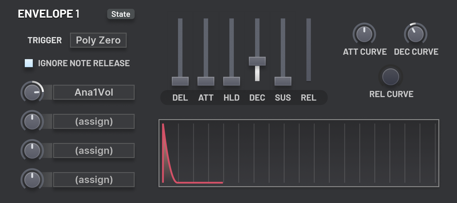
There are four envelope modulation units.
The units produce a configurable modulation value function over time.
Notably, the parameters that produce the function can be modulated as the unit is running.
There are various trigger modes that determine when the function resets to the beginning.
Delay
Determines the time between the start of the trigger and when the unit moves to the attack stage.
During the delay stage, the modulation value is constant at zero.
Attack
Determines the time between the start of the attack stage and the start of the hold stage.
During the attack stage, the modulation value starts at zero and moves up to one.
Att Curve
Determines the curvature at which the modulation value changes during the attack stage.
At −100%, the value moves quickly at first and then slows down.
At 100%, the value moves slowly at first and then speeds up.
Hold
Determines the time between the start of the hold stage and the start of the decay stage.
During the hold stage, the modulation value is constant at one.
Decay
Determines the time between the start of the decay stage and the start of the sustain stage.
During the decay stage, the modulation value starts at one and moves down to the Sustain level.
Dec Curve
Determines the curvature at which the modulation value changes during the decay stage.
At −100%, the value moves quickly at first and then slows down.
At 100%, the value moves slowly at first and then speeds up.
Sustain
Determines the value output during the sustain stage.
In this stage, the value remains constant.
The sustain stage is not left until the modulator is either retriggered, or the voice is released.
Ignore Note Release
If enabled, then note release is ignored.
If disabled, then when the note is released, the envelope will immediately switch to the
release stage, regardless of in which stage it was previously.
Release
Determines the time between the start of the release stage and the end stage.
During the release stage, the modulation value starts at whatever it was
when the release stage was entered and then moves down to zero.
Once the end stage is reached, the modulation value remains constant at zero until it is retriggered.
Rel Curve
Determines the curvature at which the modulation value changes during the release stage.
At −100%, the value moves quickly at first and then slows down.
At 100%, the value moves slowly at first and then speeds up.
Trigger
Determines what causes the envelope unit to retrigger, starting again at the delay stage.
In Poly Zero, each voice has its own copy of the envelope unit,
which starts from the beginning when the voice begins.
In Mono First, the state of the envelope is shared between all voices,
and it is retriggered when a note is pressed and no notes were previously held.
In Mono Last, the state of the envelope is shared between all voices,
and it is retriggered when a note is pressed.
Math units
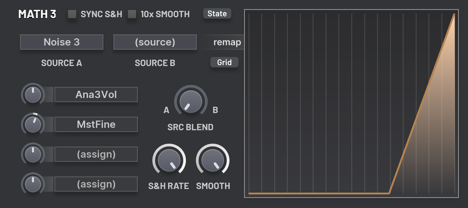
There are four math modulation units.
The units have four sub-units which are processed in series.
The first sub-unit is the source blender.
The values of two modulation sources are taken,
and they are blended together using the Src Blend parameter.
Please see the section of the modulation matrix for a description of the modulation sources.
The second sub-unit is a sample and hold unit.
This takes a sample of the incoming value at a specified interval.
The output of the unit is the currently held sample.
In this way, it behaves similarly to the Rate Reducer filter algorithm,
but typically works will lower sampling frequencies.
The third sub-unit is the smoother.
This takes the incoming values and applies a low pass filter,
smoothing out the curvature of the signal.
The final sub-unit is the remapper.
The curve graph of the right of the unit is used to remap the incoming values.
The x-axis corresponds to the input, and the y-axis corresponds to the output,
with both axes ranging from zero to one.
Source A
Determines the first modulation source as input to the source blender sub-unit.
Source B
Determines the second modulation source as input to the source blender sub-unit.
Src Blend
Determines the mix of source A and source B output by the source blender sub-unit.
S&H Rate
Determines the frequency at which the sample and hold sub-unit samples its input.
Sync S&H
Restricts the sample and hold frequencies to common multiples and fractions of the
length of a beat as determined by the host.
Smooth
Determines how much smoothing is applied in the smoother unit.
Larger values of this parameter correspond to a smoother signal.
10x Smooth
When enabled, the strength of the smoother unit
is increased by an approximate factor of ten times.
Note that this has no effect if the Smooth parameter is set to zero.
Step units
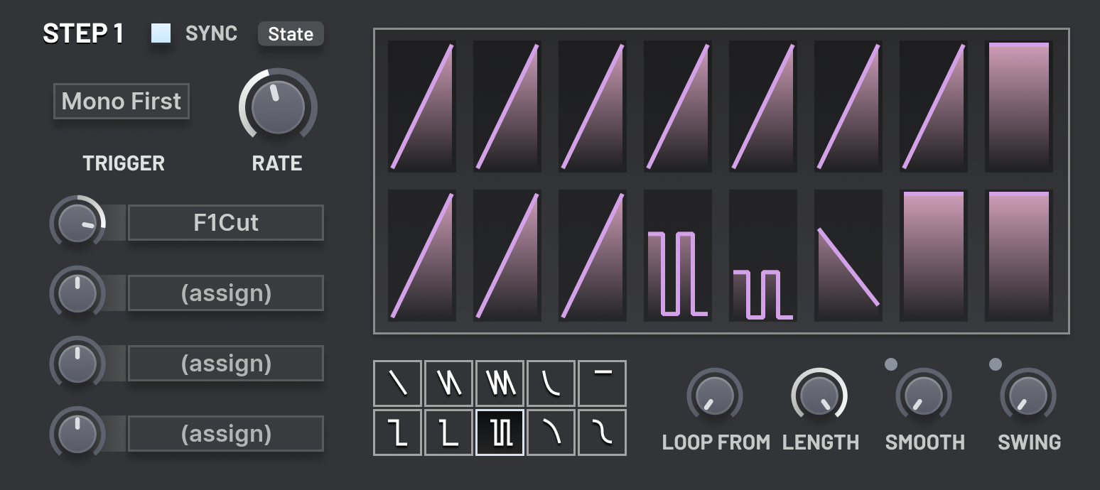
There are two step modulation units.
They each have a configurable multi-step looping pattern.
Each step has a shape, as well as a start and end value.
The shape determines how the step moves from its start to end value.
To modify the pattern, first select a shape from the selection at the bottom of the unit.
Then left or right click on a step to set the start and end value respectively,
as well as the shape.
If you are holding shift when clicking, the shape of the step will not be updated.
If you hold and drag the mouse, then if you move vertically the selected value will be updated
as you drag; if you move horizontally, you will switch between steps in the row.
If you hold shift while dragging, the modified value will be snapped to multiples of one twelfth.
This is useful if you are assigning the output of the unit to a coarse pitch parameter
and want to output semitone values in an octave.
Rate
Determines the time that each step in the sequence takes.
Once a step ends, the unit switches to the next step.
Sync
When enabled, the rate parameter will be snapped to common
multiples and fractions of the length of a beat, as specified by the host.
Loop From
Determines the step that will be returned to when the pattern loops.
Length
Determines the number of steps in the pattern.
Once the last step ends, the unit will return the step specified by the Loop From parameter.
Smooth
Smooths the output of the unit.
This occurs in a similar manner to the smoother sub-unit of the math modulators.
Swing
Determines the amount of swing applied to pairs of steps.
If there is an odd number of steps in the pattern, the last step will not be swung.
Increasing the swing increases the relative length of the first step in each pair to the second step.
Trigger
Determines what causes the unit to retrigger.
In Poly Zero, each voice has its own copy of the modulation unit,
which starts from the beginning when the voice begins.
In Poly Rand, each voice has its own copy of the modulation unit,
which starts a random position in the pattern when the voice begins.
This position will not be snapped to a step boundary.
In Mono First, the state of the pattern is shared between all voices,
and it is retriggered to the first step when a note is pressed and no notes were previously held.
In Mono Last, the state of the pattern is shared between all voices,
and it is retriggered to the first step when a note is pressed.
In Free, the state of the pattern is shared between all voices,
and it is never retriggered.
In Host Sync, the state of the pattern is shared between all voices,
and it is constantly updated so that it matches the host’s playback position.
For example, with a 8 step pattern where each step is a 1/4 beat and the host
is in beat 4 of the first bar, the current step will range from 5 to 8.
LFO units
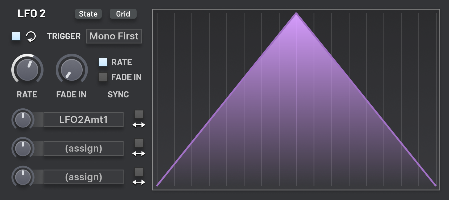
There are four LFO units.
Each loops through a drawable curve at a configurable rate to determine the output value.
This curve is found on the right side of the unit.
The x-axis corresponds to the phase of the LFO within each cycle,
and the y-axis corresponds to the output value,
ranging from zero to one for unipolar assignments,
and minus one to plus one for bipolar assignments.
See the curve editor section for more information about drawing custom curves.
The State dropdown menu provides classic LFO shape presets,
such as a sine waveform and pulses.
The three modulation destinations for each LFO have a bipolar toggle box
next to them. When this is enabled, the LFO will apply both negative
and positive offsets to the destination parameter.
When this is disabled, the LFO will only apply positive offsets
(or if the assignment amount is negative, only negative offsets)
to the destination, just like other modulation units.
Loop
The looping arrow icon indicates the loop toggle box.
When enabled (the default), the LFO will loop once it reaches the end of its first cycle.
When disabled, the LFO will not loop, making it behave like a one shot envelope.
Trigger
Determines what causes the LFO to retrigger.
In Poly Zero, each voice has its own copy of the modulation unit,
which starts from the beginning when the voice begins.
In Poly Rand, each voice has its own copy of the modulation unit,
which starts a random position in the cycle when the voice begins.
In Mono First, the phase of the LFO is shared between all voices,
and it is retriggered to the first step when a note is pressed and no notes were previously held.
In Mono Last, the phase of the LFO is shared between all voices,
and it is retriggered to the first step when a note is pressed.
In Free, the phase of the LFO is shared between all voices,
and it is never retriggered.
In Host Sync, the phase of the LFO is shared between all voices,
and it is constantly updated so that it matches the host’s playback position.
For example, if the rate is set to 2 bars and the host is at the start of bar 4,
the phase will be halfway through the cycle.
Rate
Determines the length of a single cycle of the LFO.
Rate Sync
When enabled, the Rate parameter will be locked to common
multiples and fractions of the length of beat, as determined by the host.
Fade In
Determines how long the amplitude of the LFO takes to fade in from zero to its maximum value.
The parameter is bipolar-aware, so it will behave as expected
for both unipolar and bipolar assignments.
Fade In Sync
When enabled, the Fade In parameter will be locked to common
multiples and fractions of the length of beat, as determined by the host.
Matrix
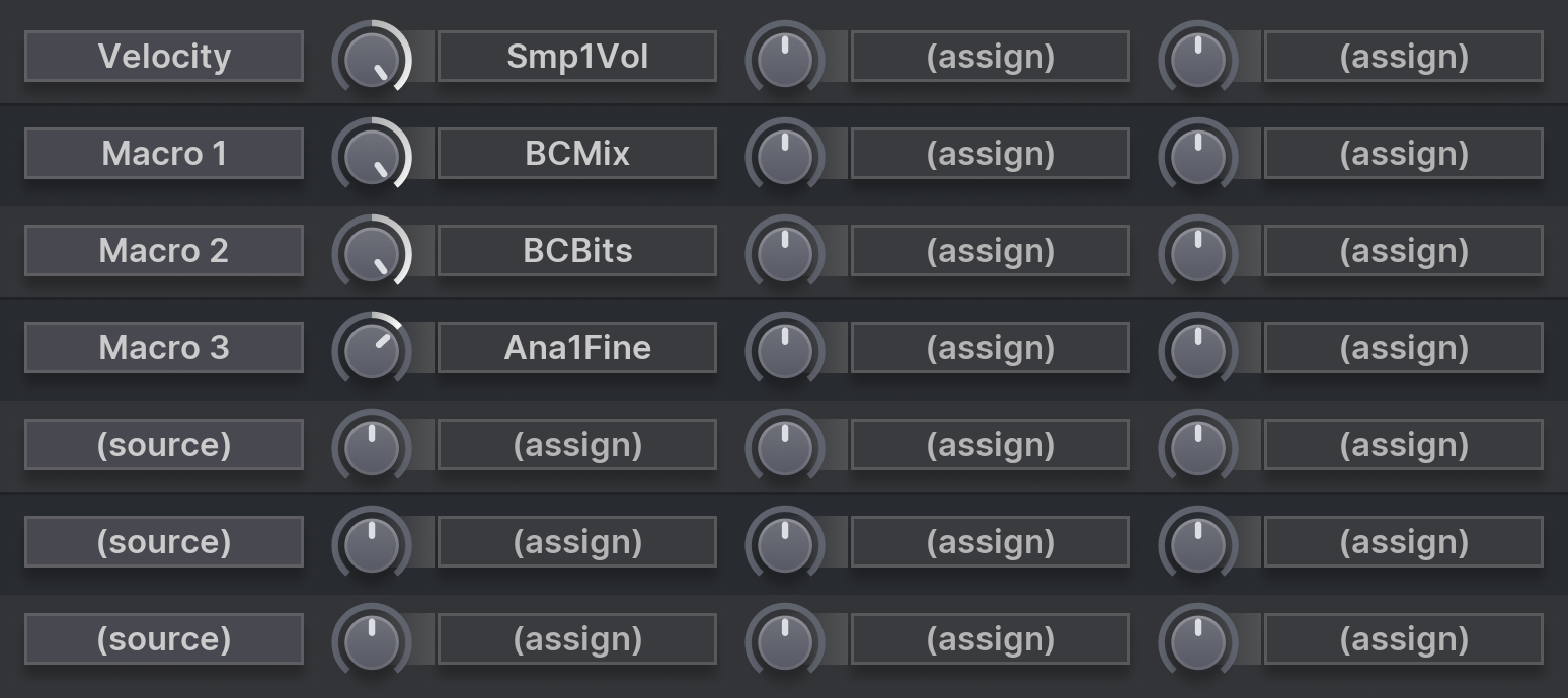
The modulation matrix consists of seven rows.
Each row has a source and three destinations.
The value from the source is propagated to each of three destinations with the selected amount.
The following is a description of each of the selectable sources;
these are same sources that are available in to the math modulation units.
LFO 1–4
The unipolar output of the given LFO unit.
LFO 1–4 (bi)
The bipolar output of the given LFO unit.
Env 1–4
The output of the given envelope unit.
Math 1–4
The output of the given math unit.
Step 1–2
The output of the given step unit.
Amp Env
The output of the amp envelope.
Key Track
The pitch of the note.
First, the sum of the raw note pitch, pitch expression, portamento offset, and MIDI pitch bend is calculated.
Then, this value is linearly scaled
so C5 corresponds to a value of 0.5,
C9 corresponds to a value of 1.0,
and C1 corresponds to a value 0.0.
Pitches outside the range C1 to C9 will be clamped so that the key track value remains between 0.0 and 1.0.
Velocity
The velocity of the note.
Important: In the FL Studio native version of the plugin,
the velocity of all notes is multiplied by the Channel Volume.
This is a behaviour of FL Studio and cannot be disabled.
Mod Wheel
The current value of the MIDI mod wheel.
Important: In the FL Studio native version of the plugin,
this is assigned to the Mod X parameter in the piano roll, because
FL Studio does not give native plugins access to the MIDI mod wheel.
MIDI Pressure
The current value of the MIDI pressure/aftertouch.
Important: In the FL Studio native version of the plugin,
this is assigned to the Mod Y parameter in the piano roll, because
FL Studio does not give native plugins access to the MIDI pressure.
Per Note Rnd 1–4
When a new voice is played, it is assigned four randomly generated values.
These sources give access to these values.
Noise 1–4
For each update of the modulation values, four random noise samples are generated.
These sources give access to these values.
Macro 1–4
The current value of the macro parameters.
Seq 1–2 Expr
The chosen expression value for the current sequencer step.
Note Is Held
This is zero if the currently processed voice is attached to a note that been released,
and one if the voice is attached to a note that is still held.
Note Held Count
This is zero if no notes are held.
This is a half if one note is held.
If there are n voices held,
then the value is 1−2−n.
This means that each additional note adds half the value of the previous note to the sum,
getting closer and closer to one, but never quite reaching it.
Effects
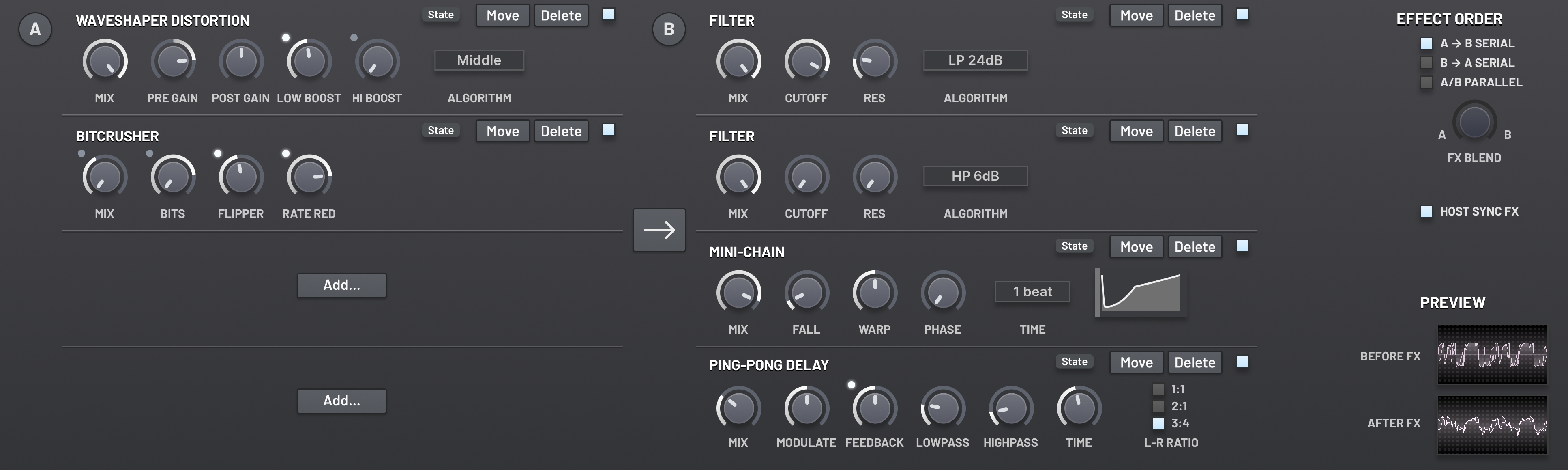
Altitude comes equipped with 17 types of the effect units.
You can configure two effect chains, chain A and chain B.
Each chain has 4 slots for effect units.
Each effect unit type can be added up to three times across both chains.
You can also configure the processing order of the two chains.
To configure the effects, select the Effects page from the switcher in the top-right corner of the interface.
The effects are applied to all voices together.
In terms of the overall signal flow of the audio engine,
the effects take place directly after the amplitude and before the master volume.
Effect Order
This option determines the processing order of the chains.
A→B Serial will first apply the four effects in chain A to the input signal,
from top to bottom. Then it will apply the effects in chain B.
B→A Serial is similar, except it runs chain B first, and then A.
A/B Parallel duplicates the input and sends a copy to each chain for processing.
Then the outputs of the chain are combined, based on the FX Blend parameter.
FX Blend
This parameter is only used in the A/B Parallel effect ordering.
It determines the relative mix of the output of chain A and chain B
that will be sent to the master volume, and then subsequently to the host.
Host Sync FX
When enabled, the mini-chain and trancegate units will be synchronised
with the host’s playback position.
When disabled, these effects are retriggered when a ‘first note’ is played,
i.e. when no notes are held and then a new note is pressed.
Important: This setting is not a BPM sync control.
It is a phase synchronisation mechanism.
Certain effect units can be configured to synchronise with the host’s BPM separately.
Trancegate
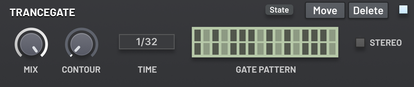
The trancegate applies an on-off patterns of steps to the volume, producing a sharp, rhythmic
effect. You can pick between a mono or stereo pattern; the latter lets you control each stereo
channel separately.
Mix
The amount of the output from the trancegate to be mixed with its input. 0% effectively
disables the trancegate, while 100% takes only the signal from the trancegate.
Contour
Controls how sharp the gate is. At 0%, the gate immediately opens and closes with
each step. At 100%, the gate smoothly moves from one step to the next.
Time
The length of each step, in fractions of a bar. This is always synchronized to the host’s
BPM.
Gate Pattern
The pattern of the gate. Left click a step to toggle it on or off.
Stereo
When enabled, the gate pattern can be set differently for the left and right stereo
channels. The top row of steps on the gate pattern represents the left channel, and the bottom
row represents the right channel. When disabled, the gate pattern can only be edited so that
both channels are either on or off at the same time for a given step.
Parametric EQ
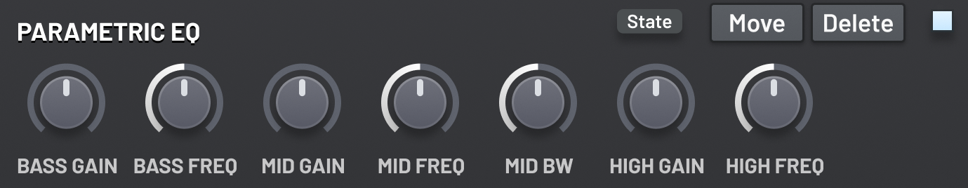
The EQ allows you to boost or cut the gain of three different frequency bands. You can
configure the frequencies selected by each band, and you can also change the band width of
the mid frequency band.
Bass Gain
The amount in decibels to boost or cut the bass frequencies by. Specifically, this
is a low-shelf EQ.
Bass Freq
The frequency cutoff point selected for the bass gain. All frequencies below
this point will be affected.
Mid Gain
The amount in decibels to boost or cut the mid frequencies by. Specifically, this is
a peaking EQ.
Mid Freq
The frequencies selected for the mid gain. The frequencies around this point
will be affected.
Mid Band Width
The size of the mid band. This controls how far away from the Mid
Frequency value frequencies will still be affected.
Important: The minimum value of this parameter is probably more extreme
than you are used to in other plugins. It can produce a single ringing tone
that decays very slowly.
High Gain
The amount in decibels to boost or cut the high frequencies by. Specifically, this is
a high-shelf EQ.
High Freq
The frequency cutoff point selected for the high gain. All frequencies above
this point will be affected.
Phaser
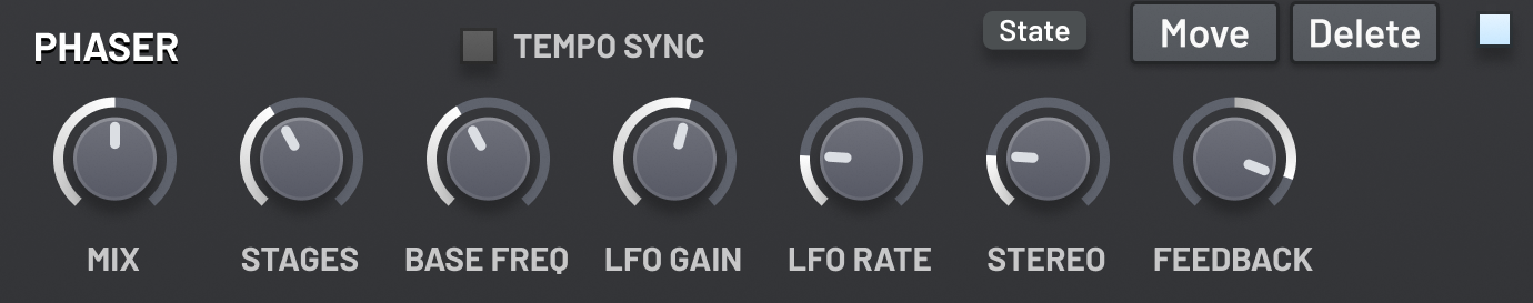
The phaser sends the signal through a variable number of all pass filters. The cutoff is
modulated by a built-in LFO. This creates interesting phasing effects, causing different
frequencies to be attenuated over time.
Mix
The amount of the output from the phaser to be mixed with its input. 0% effectively
disables the phaser, while 100% takes only the signal from the phaser.
Stages
The number of all pass filters to send the signal through.
Base Freq
The base cutoff frequency of the filters.
LFO Gain
The range around the base frequency that the LFO will sweep in.
LFO Rate
How quickly the LFO runs. A triangle LFO shape is used.
Stereo
Adjusts the base frequency between the stereo channels slightly.
Feedback
Sends the phaser’s output back into itself. This creates a different sound
depending whether the feedback is positive or negative.
Tempo Sync
When enabled, the speed of the LFO is locked to common fractions and multiples of the
length of a beat, as determined by the host’s tempo.
Chorus
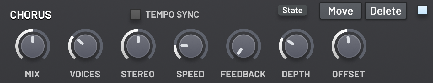
The chorus effect simulates multiple voices playing the same note with slightly different pitch
and stereo spread, achieving a similar result as unison (see the Generators section of this document).
It works by keeping a small buffer of the input signal, and then averaging from multiple
positions in the buffer, with the specific positions modulated by LFOs.
Mix
The amount of the output from the chorus to be mixed with its input. 0% effectively
disables the chorus, while 100% takes only the signal from the chorus.
Voices
The number of voices to simulate.
Stereo
Offset the reading position in the buffer between the left and right channels.
Speed
Controls the speed of the LFOs. With large values, you will likely want to decrease the
Depth, otherwise the resulting sound will be highly chaotic and noisy.
Feedback
Mix some of the output from the chorus back into itself.
Depth
Controls the size of the buffer kept, and in turn, the range of the LFOs. Larger values
will produces a more intense chorusing result.
Tempo Sync
When enabled, the speed of the LFO is locked to common fractions and multiples of the
length of a beat, as determined by the host’s tempo.
Compressor
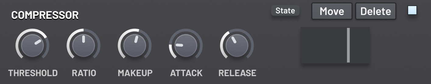
The compressor automatically reduces the volume of your patch once it exceeds a threshold
value. You can configure the time it takes to engage once the threshold is exceeded and how
long it takes to disengage after the volume goes below the threshold. Overall, this has the
effect of reducing the dynamic range of your sound; loud parts will no longer be as loud, and
thus quiet parts will be less quiet in comparison. The compressor is a powerful tool. To produce
pleasing results, remember that moderation is key.
Threshold
The amplitude in decibels which must be exceeded for the compressor to engage.
Ratio
The ratio of amplitude over the threshold in the input vs output signal. When the input
signal is below the threshold the output and input amplitude are the same. When the input
signal is above the threshold, the following algorithm is used to calculate the output amplitude
from the input amplitude: multiply the ratio with the amount the input exceeded the threshold by,
and then add this to the threshold.
For instance, when the ratio is set to 1:1, the compressor will have no effect.
As the ratio dial is turned to larger ratio, the compressor will reduce the volume of signal more,
and thus the effect will be greater. But note that regardless of the ratio, as long as the signal
stays above the threshold, the compressor will not reduce the volume of the signal below the
threshold.
Makeup
Gain applied to the output signal, after it has been processed by the compressor.
This is used to “correct” the amplitude of the signal, so that the maximum amplitude is the
same as it was before the compressor was applied, meaning that the remaining resultant
effects is that the quiet parts have become louder, while the louder parts have remained
constant.
Attack
The time it takes for the compressor to engage once the signal passes the threshold.
The longer the attack time, the longer the “snap” at the start peaks as they are brought down
in volume.
Release
The time it takes for the compressor to disengage once the signal is no longer above
the threshold. Making the release time very short can cause a distortion-like effect. Making the
release time too long nullifies the effect of the compressor, as it will apply a constant gain to
the signal, even in the quiet parts.
Reverb
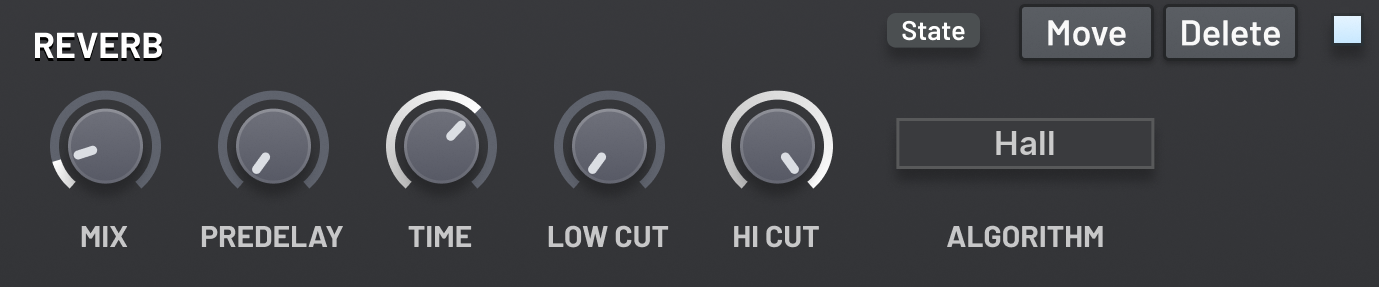
The reverberation unit creates a simulation of the blurring of a sound’s tail when played in a
large acoustic space, where individual echoes are in such high number they become indistinct.
Pre-delay
Controls how long before the reverberations begin.
Time
Determines the approximate length of the reverb tail, in seconds.
This is measured as the time the amplitude takes to decay by roughly 60dB.
Mix
The amount of the output from the reverb to be mixed with its input. 0% effectively
disables the reverb, while 100% takes only the signal from the reverb.
Algorithm
Selects the acoustic space to simulate. This affects the length, brightness and
complexity of the reverb tail. It is recommended that you mostly ignore the names and details
of the algorithms, and instead choose whichever sounds best for your patch by ear!
Low Cut
Determines the cutoff frequency of a high pass filter
used to remove the low frequencies of the wet reverb signal.
This is a simple 6dB per octave one-pole filter,
with the gentle cutoff slope.
High Cut
Determines the cutoff frequency of a low pass filter
used to remove the high frequencies of the wet reverb signal.
This is a simple 6dB per octave one-pole filter,
with the gentle cutoff slope.
Ping-Pong Delay
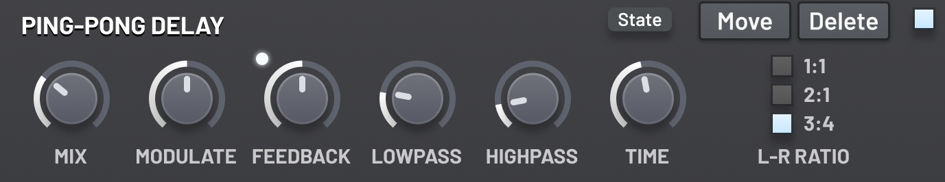
This unit contains a signal delay line.
Each stereo channel is sampled from a different point on the line,
creating a simple rhythmic pattern between the left and right channel.
Feedback is sent from the end of the line back to the start.
Feedback
Controls the difference in amplitude between echoes.
At 100%, the echoes will not decay away. At 0%, the second echo will not be audible.
Low Pass
Controls the cutoff point of a low pass filter applied to the feedback. The higher this
value is set, the lower the cutoff point is moved, thus increasing the apparent damping of the
signal.
High Pass
Controls the cutoff point of a high pass filter applied to the wet signal. The higher
this value is set, the higher the cutoff point is moved. This filter is only applied to the final wet
signal being mixed into the result; it does not affect the feedback signal.
Algorithm
Selects the acoustic space to simulate. This affects the length, brightness and
complexity of the reverb tail. It is recommended that you mostly ignore the names and details
of the algorithms, and instead choose whichever sounds best for your patch by ear!
Mix
Controls how much of each delay line to mix back into the dry signal. Unlike the mix
controls on other effect units, changing this only affects the amplitude of the wet signal, and
the dry signal remains at full volume.
If this is set to zero, evenly if just briefly through modulation,
the delay line is immediately cleared to silence.
Time
Controls the length of each delay line, relative to the host’s tempo.
Modulate
Slightly modulates the length of the delay line using a LFO to
reduce phasing issues that can occur when echoes stack up on top of each other when a note
is held long enough.
L-R Ratio
Controls the ratio of the positions in the delay line where the left
and right channel samples are read from.
Sub Oscillator
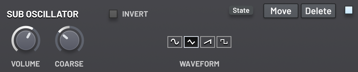
This unit contains a naive digital oscillator intended for use as a sub layer.
As it can be placed anywhere in the effects chain, you can control precisely
what effects are and aren’t applied to it.
As a naive digital oscillator, if you choose to use it for higher pitched notes,
there will be very noticeable aliasing artifacts!
This should not occur when used as a sub, especially with lower volumes.
However if you ever need to create some disharmonius digital whines, then here’s your chance!
Volume
Determines the amplitude of the oscillator for each voice to be mixed in with the input.
Coarse
The coarse pitch of the oscillator, relative to the note’s pitch.
This parameter is snapped to semitones before modulation.
After modulation, no snapping is applied.
Invert
When enabled, the output of the oscillator has its polarity inverted.
If you are using the oscillator as a sub,
you should take care not to accidentally remove the fundamental frequencies
from the main generators!
Use this toggle to ensure you are in phase with them.
Waveform
The waveform of the oscillator.
You can choose between Sine, Triangle, Sawtooth and Square.
The waveforms are nearly identical to the main virtual analog oscillators,
except the Sawtooth and Square waveforms will be aliased,
allowing you to produce incredibly rich sub tones.
Pattern Delay
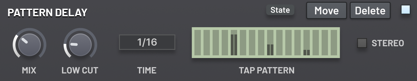
The pattern delay unit contains a delay line into which the input is fed.
There are 16 evenly spaced taps along the line.
The tap pattern is used to determine the gain applied to each of the taps,
optionally with a different gain for each stereo channel.
The output of the taps is then sent through a filter and finally mixed with the input.
Mix
Determines the relative proportion of the dry and wet signal to output from the effect unit.
Note that this behaves different to the Mix parameter of the ping-pong delay,
where the dry signal is always output at 100% amplitude.
With the mix set to 100% on the pattern delay, the dry signal will be silent.
If the mix parameter is ever set to 0%, even if just briefly through modulation,
the delay line will be immediately cleared to silence.
Low Cut
The cutoff frequency of a one-pole high pass that
is applied to the wet signal before mixing with the dry.
Time
Determines the spacing between the taps.
Multiply this by 16 to determine the total length of the delay line.
This parameter is locked to common multiples and fractions of the length of a beat, as determined by the host.
Tap Pattern
Determines the amplitude of the 16 taps.
Left click and drag to set the amplitude for the left stereo channel,
or right click and drag for the right stereo channel.
If Stereo is enabled, then the right channel amplitudes will not be used;
the left channel amplitudes will determine their values.
Stereo
If enabled, the tap pattern can have different amplitudes at each tap
for the left and right stereo channels.
If disabled, the amplitudes of the left stereo channel will be used for the right channel taps as well.
Two-Tap Delay
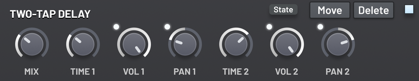
The two-tap delay unit contains a delay line into which the input is fed.
The delay line is exactly 4 beats long, where the length of a beat is determined by the host’s tempo.
You control two taps that read from the delay line that will be mixed with the input.
Unlike the other delay effect units, you can modulate the time parameter of the taps,
which allow for the creation of some very interesting effects.
If you need more than two taps, remember you can add up to three instances of this effect unit into the chain!
Mix
Determines the relative proportion of the dry and wet signal to output from the effect unit.
Note that this behaves different to the Mix parameter of the ping-pong delay,
where the dry signal is always output at 100% amplitude.
With the mix set to 100% on the pattern delay, the dry signal will be silent.
If the mix parameter is ever set to 0%, even if just briefly through modulation,
the delay line will be immediately cleared to silence.
Time 1/2
The position of the taps into the delay line,
as a fraction of the total line length (4 beats).
This parameter can be modulated!
Volume 1/2
The gain of each of the taps.
Pan 1/2
The stereo panning of each of the taps.
Stereo Enhancer
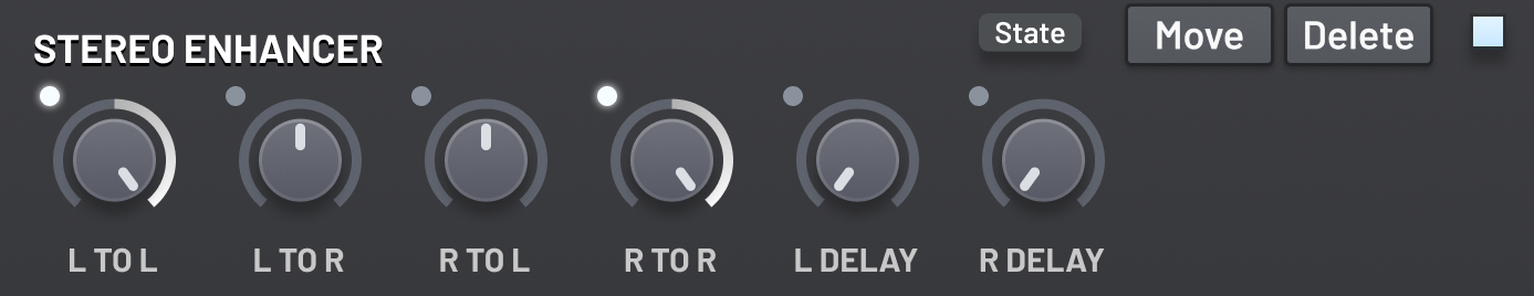
The stereo enhancer unit applies a customisable delay to each of the stereo channels independently.
Then, it mixes the channels together using customisable weights for each of the four routing pairs.
L To L
Determines the amplitude and polarity of the input left channel sent to the output left channel.
L To R
Determines the amplitude and polarity of the input left channel sent to the output right channel.
R To L
Determines the amplitude and polarity of the input right channel sent to the output left channel.
R To R
Determines the amplitude and polarity of the input right channel sent to the output right channel.
L Delay
The length of the delay line the input left channel is sent through.
This delay occurs before the channel mixing.
R Delay
The length of the delay line the input right channel is sent through.
This delay occurs before the channel mixing.
Mini-Chain
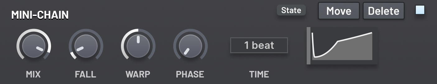
The mini-chain applies a repeating envelope to the input’s amplitude,
simulating the ‘pumping’ effect of sidechain compression with a repeating input.
Mix
Determines the maximum amount of volume reduction applied by the envelope.
Fall
Determines how long the envelope takes to fall to the minimum value
from the start of the loop.
Warp
Warp the envelope so that it changes quicker near the start or near the end.
Phase
Determines the starting phase in the loop when the unit is retrigger.
See the Host Sync FX parameter for information about when the mini-chain units are retriggered.
Time
Determines the time for one loop of the envelope.
Five-Band EQ
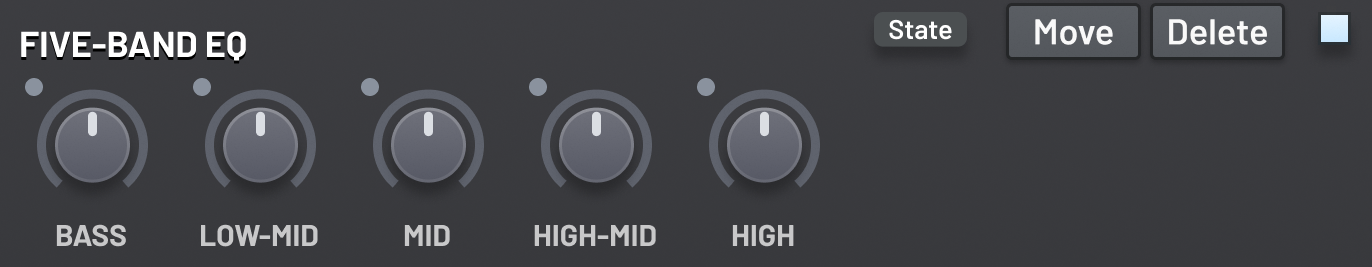
This is an equaliser with five bands, each with fixed type and frequency.
You can control the amplitude gain or reduction for each band.
Bass
Determines the gain of a low shelf placed at 140 Hz.
Low-Mid
Determines the gain of a peak placed at 250 Hz.
Mid
Determines the gain of a peak placed at 920 Hz.
High-Mid
Determines the gain of a peak placed at 3.2 kHz.
High
Determines the gain of a high shelf placed at 6.2 kHz.
Filter
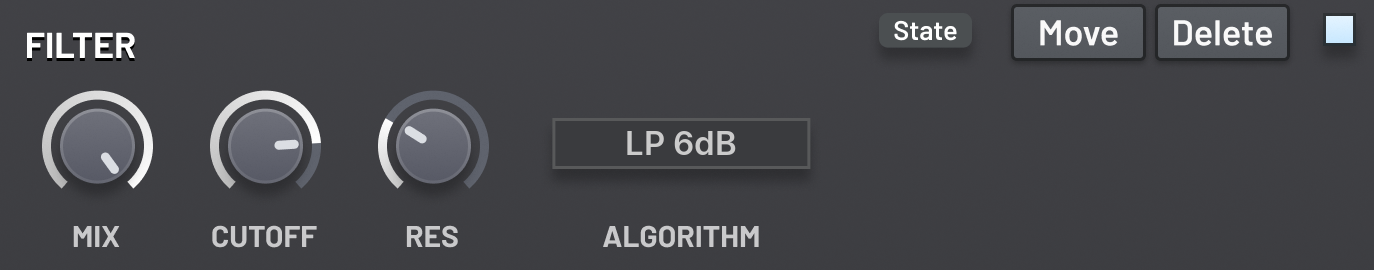
This unit contains a filter similar to the main filters, F1 and F2,
however less algorithms and types are available, since some of them would be redundant with the
other effect units (like the phaser).
See the section of the filters for more information about how this effect unit works,
including details of the Cutoff and Resonance parameters.
Mix
The amount of the output from the filter to be mixed with its input. 0% effectively
disables the filter, while 100% takes only the signal from the filter.
Be mindful of phasing issues that can occur when modifying the mix parameter;
the filter algorithms used by the unit will modify the phases of different
frequencies by different amounts, which will have possibly unintended
consequences when mixing with the original signal.
Bitcrusher
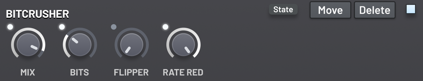
The bitcrusher unit allows you to reduce the fidelity of the digital input signal.
But beware: this will produce lots of digital artifacts like aliasing!
It is best used either in moderation, or for particular retro stylistic effect.
Mix
The amount of the output from the bitcrusher to be mixed with its input. 0% effectively
disables the bitcrusher, while 100% takes only the signal from the bitcrusher.
Bits
The number of bits that the input signal will be snapped to.
This reduces the number of distinct amplitude values a sample can have.
This is essentially a very rudimentary form of distortion.
Flipper
Select a bit to flip in the input signal.
A digital signal is made up of samples which are in turn made up of bits.
Each bit is either set or clear. Flipping a bit switches its state to the other one.
The bits are used determine to the amplitude of the sample.
Each bit is assigned a jump in amplitude.
To determine the sample’s amplitude, the amplitudes corresponding to set bits are added together,
and the clear bits are ignored.
The assigned amplitude jumps are specifically chosen so that a sample can take any amplitude
(up to some limit of precision).
The higher bits encode a larger jump in amplitude,
so flipping them will have a more noticeable effect.
Rate Reducer
See the section on the filters for a description of the rate reducer algorithm.
This parameter behaves identically to the Cutoff parameter of a filter
with the rate reducer algorithm selected.
Flanger
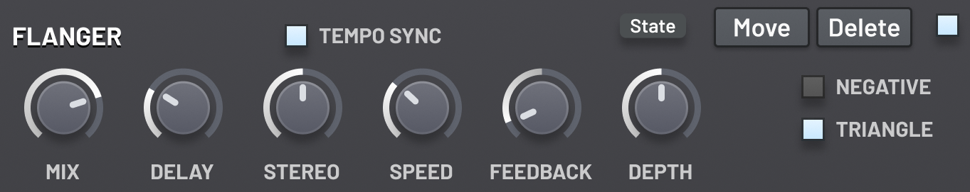
The flanger unit is based around a comb filter (short delay line with feedback)
where the length of the line is modulated by an LFO.
It is similar in nature to the phaser and chorus effects,
but nonetheless has a very distinctive sound.
Mix
The amount of the output from the flanger to be mixed with its input. 0% effectively
disables the flanger, while 100% takes only the signal from the flanger.
Negative
When enabled, the polarity of the wet signal is flipped
before it is mixed with the dry signal.
Delay
Determines the minimum length of the delay line.
Depth
Determines the amount by which the LFO modulates the delay line’s length.
The maximum length of the delay line is calculated as the sum of the delay and the depth.
Stereo
Causes the stereo channels to differ in sound by shortening the delay line used for the right channel.
At 100%, the delay line’s length is cut in half.
Feedback
The amount of feedback from the end of the delay line to the start.
This control is bipolar, so that you can have both negative and positive feedback.
The polarity of the feedback can greatly influence the sound.
Typically, negative feedback produces more square-wave-like sounds.
Speed
Determines the speed of the LFO that modulates the delay line length.
Triangle
When enabled, the LFO follows a triangle wave shape.
When disabled, the LFO follows a sine wave shape.
Tempo Sync
When enabled, the speed of the LFO is locked to common fractions and multiples of the
length of a beat, as determined by the host’s tempo.
Waveshaper Distortion
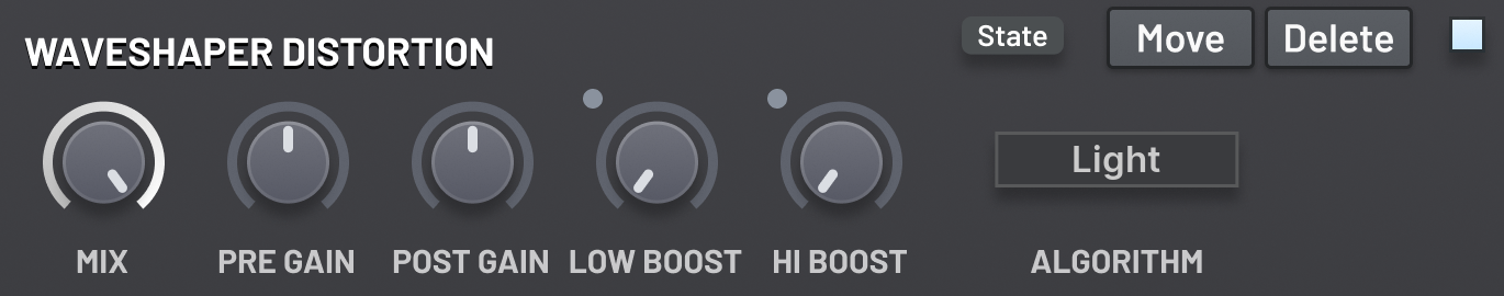
This distortion unit provides a variety of waveshaping algorithms to apply to the input signal.
You can also apply a gain boost to the low or high frequencies before they are processed
by the algorithm to increase how much they will be distorted.
Mix
The amount of the output from the unit to be mixed with its input. 0% effectively
disables the unit, while 100% takes only the signal from the unit.
Pre Gain
Determines the gain applied to the signal before the distortion algorithm is applied.
Post Gain
Determines the gain applied to the signal after the distortion algorithm is applied.
Low Boost
Boosts frequencies below 500 Hz before the distortion algorithm is applied
by up to 6 dB.
Hi Boost
Boosts frequencies above 500 Hz before the distortion algorithm is applied
by up to 6 dB.
Algorithm
The distortion algorithm. All of these algorithms are waveshapers.
That means that they are applied to each sample of the input individually
and are unaware of the surrounding samples.
The Light, Soft, Middle and Hard algorithms
are modelled closely after a popular digital synthesizer.
They are asymmetric waveshapers, meaning they distort samples above and below zero differently.
This allows them to introduce even harmonics, whereas typically waveshapers can only introduce
odd harmonics (producing square-wave-like sounds).
However as a side effect this will introduce a DC offset.
You can put a high pass filter after the distortion unit to remove the offset, if needed.
The Digital algorithm clamps samples to a certain range.
The Fold algorithms apply periodic mathematical functions to the input.
This create interesting disharmonics as the pre gain is increased.
Sequencer
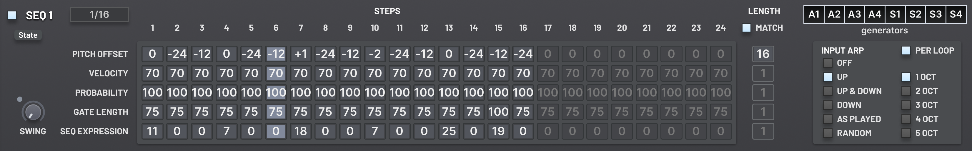
Altitude sports two polyrhythmic sequencers.
Each sequencer has a builtin arpeggiator.
The arpeggiator determines which of the currently held notes to use as the pitch and velocity base.
The sequencer has 5 rows of steps in its pattern.
Each row can have a different number of steps, between 1 and 24.
Each row determines some property of the played voices.
Every time the sequencer ticks, each row is moved forward one step,
and any rows that have reached their end go back to the start.
Depending on whether the Per Loop option is enabled,
the arpeggiator will go to the next note either on each sequencer tick,
or only when the pitch row loops.
Pattern rows
Pitch Offset
The offset to the pitch base in semitones.
Velocity
The velocity multiplier, relative to the velocity base.
At 70, the velocity is left unchanged.
Probability
The probability, as a percentage, that the step will trigger.
At 0%, the step will always be silent.
Gate Length
The portion of the step, as percentange, for which the step will sound.
At 0%, the step will be silent.
If this is 100% and Legato is enabled, the step will be joined with the following step.
Seq Expression
The expression parameter for the step.
This can be routed to parameters in the Mod Matrix,
or using the Math modulation units.
Sequencer parameters
Enable
Determines whether the sequencer will be used.
For further details into how incoming note events are routed,
see the Signal flow section.
Rate
Determines the length of each step as a fraction of the length of a bar.
The length of a bar is determined by the host’s tempo.
Swing
Swings pairs of steps.
By default, the length of each step is determined exactly by the Rate parameter.
However as the Swing is increased, the first step in each pair of notes becomes longer,
and the second step is made shorter.
But the overall length of each pair of notes will remain unchanged.
Pairs can span steps looping back to the start of their row.
Row Lengths
Determines the length of each row, as a number of steps.
This can range from 1 up to 24.
Each row can have a different length, creating polyrhythms.
Match Lengths
When enabled, all rows will have the same number of steps
as the Pitch Offset row.
Typically, you should enable this if you only want to use the arpeggiator and not the sequencer.
Generators
Select the generators that will be active for the voices output by this sequencer.
The deselected generators will be silent for this sequencer’s voices,
but they may still be able to play for direct play or for voices from the other sequencer.
Indeed, any generators not assigned input from a sequencer will be in direct play mode.
That is, they will behave as if no sequencers are enabled.
Important: You must make sure that the corresponding generators are actually enabled,
and that they are set to receive voices in the octave ranges that the sequencer will be outputting!
Arpeggiator parameters
Per Loop
When enabled, the arpeggiator will step every time the Pitch Offset row
of the sequencer loops back to the start.
When disabled, the arpeggiator will step every time the sequencer steps.
Direction
Determines the order in which the input notes will be moved through.
Every time the arpeggiator steps, a new input note is selected.
Once all notes have been iterated through, the pattern repeats
(possibly with a different octave offset; see the Octaves parameter).
The different direction modes are detailed in the next subsection.
Octaves
The number of octaves that will be arpeggiated through.
The next octave is switched to when the arpeggiator repeats its pattern.
After all octaves are played, it returns to the beginning.
This can be changed from 1 octave up to 5 octaves.
Important: Octaves are always arpeggiated upwards, regardless of the Direction setting.
Arpeggiator directions
Off
The arpeggiator is disabled.
Only the first input note is used.
This also disables the octave switching.
Up
The notes are sorted by their pitch,
and are iterated through in ascending order.
If a new input note is played in the middle of the pattern,
the arpeggiator will fit it into the correct position.
Down
The notes are sorted by their pitch,
and are iterated through in descending order.
If a new input note is played in the middle of the pattern,
the arpeggiator will fit it into the correct position.
Up & Down
This is a mix of the Up and Down modes.
First, the notes are played in ascending order by pitch,
and then they are played in the reverse order.
But the top and bottom notes are not duplicated.
As Played
The order in which the input notes were first pressed
determines the order of the arpeggiator’s pattern.
Random
At each arpeggiator step,
a new input voice is chosen at random.
Sequencer actions
A set of actions that can be applied to the sequencer pattern are made available from the State
menu for the sequencer, accessible in the top-left corner of the unit’s interface.
Randomize pitch (major)
The pitch offset row is randomized to contain semitone offsets
that are only accessible in a major scale.
Randomize pitch (minor)
The pitch offset row is randomized to contain semitone offsets
that are only accessible in a minor scale.
Randomize pitch (pent)
The pitch offset row is randomized to contain semitone offsets
that are only accessible in a pentatonic scale.
Randomize velocities
The velocity row is randomized.
Randomize gate lengths
The gate length row is randomized.
Randomize probabilities
The probability row is randomized.
Randomize expressions
The sequencer expression row is randomized.
Transpose down 1 oct
All the pitch offset steps are decreased by 1 octave (12 semitones).
Transpose up 1 oct
All the pitch offset steps are increased by 1 octave (12 semitones).
Transpose down 1 st
All the pitch offset steps are decreased by 1 semitone.
Transpose up 1 st
All the pitch offset steps are increased by 1 semitone.
Patch ideas
- Try modulating the rate of an LFO using an envelope.
- Try modulating an envelope’s parameter with itself.
- Try modulating the Stall parameter on a sample layer with the Note On modulation source to trigger the sample only when the note is released.
- Try selecting the Select one at random keyboard mapping mode for the oscillators, and put a different waveform in each.
- Try setting the Filter Mix of a generator to 50–50, and then inverting the output of Filter F2 using the volume parameter. Then you can create interesting phasing effects and new filter types by modulating the cutoff of the filters together, and selecting different algorithms for each.
- Try using a sample as an FM source. And then resample it, using the Export as sample… option in the patch menu. And keep repeating!
- Try using a sample as an FM source with the stall option enabled and the start randomness set to 100%. Then each note will effectively get a random FM source.
- Try using the Chorus effect unit instead of unison.
- Try setting the Chorus speed to the maximum and the depth to around 3%.
- Try placing the bitcrusher with extreme settings after a delay or reverb unit. Then, use the parallel effect ordering to blend in some of the dry signal, perhaps even modified with a phaser or chorus unit.
- Try sending white noise in the a band pass filter with high resonance and maximum key track.
- Try putting multiple delay effect units together in series, with slightly different time parameters. If all the times are very short, you will get a pseudo-reverb effect.
- Try putting a stereo enhancer with the all the gains set to 0%, followed by a sub oscillator one octave higher than the main generators, and finally a reverb with 100% mix. Then use the parallel effect ordering to let the main generators through on the other chain. This creates a faux shimmer reverb.
- Try modulating the parameters of the Mini-Chain effect using an LFO running at twice the speed of the effect unit.
- Try creating a unison stacked oscillator, but set the detune to 0%. Then apply Chaos or LFO … modulation. Since these FM sources run per-unison voice, this will create some interesting effects. Try setting the LFO rate really fast for further FM-esque sounds.
- Try evolving or randomizing the patch.
- Try using unison on an oscillator with retrigger enabled. Then use a note random modulation source on the detune amount.
- Try setting the global coarse pitch snapping to octaves, and then modulate it with an LFO to create chiptune-like effects.
- Try setting all oscillators to a square waveform with different fine tunings, and then assign a slightly different LFO to each oscillator’s pulse width.
- Try adding an extra sample layer to an existing patch. Or swap out the samples used. Many of the samples were chosen so that they would be good for fine tuning the timbre of patches.
- Try changing your init patch! Since it’s the first thing your hear when you load the synth, different settings will inspire you to take different sound design paths.
- Try copying and pasting a generator and tuning it one octave up.
- Try modulating the cutoff of a comb filter for sync-like effects.
Additional information
FL Studio native format
After updating FL Studio to a new major version (e.g. 20 to 21), you will need to reinstall Altitude
so that FL Studio can find the plugin. This is because each major version of FL Studio looks for native plugins
from a different folder.
Manual uninstallation
On Windows, advanced users can manually uninstall Altitude by deleting the following files and folders:
- %COMMONPROGRAMFILES%\CLAP\Altitude.clap
- %COMMONPROGRAMFILES(X86)%\CLAP\Altitude (32-bit).clap
- [FL Studio installation folder]\Plugins\Fruity\Generators\Altitude
- %APPDATA%\NakstAudioPlugins\Altitude Standalone.exe
- %APPDATA%\Microsoft\Windows\Start Menu\Programs\Altitude Standalone.lnk
- HKEY_CURRENT_USER\SOFTWARE\AltitudeSynthesizer
- HKEY_CURRENT_USER\SOFTWARE\NakstAudioPlugins
Crash reports
On Windows, Altitude automatically saves crash reports to your Downloads folder.
The report will be created the next time you load Altitude after the crash.
A crash report will be created even if Altitude was not responsible for the crash;
it might have been caused by your host software or a different plugin that was running.
If you believe Altitude to be responsible for the crash,
please submit the report to the developers for further investigation.
License information
Altitude Synthesizer end-user license agreement (EULA):
- The Software ("Altitude Synthesizer") is Copyright (C) 2022-2023 by nakst.
- The User (you) is granted a personal, non-transferable license for use of the Software, including commercial use. This license does not grant use of the Software for anyone other than the single User.
- The User may not reverse-engineer, disassemble or decompile the Software, except where permitted by statutory law. The User may not modify or tamper with the Software.
- The User of the Software may not redistribute, sublicense, distribute or rent the Software. The User is permitted to make unlimited copies of the Software for use on other devices or backup, provided that (a) the copies will be exclusively used by the User, and (b) are not accessible to anyone other than the User.
- The Software may not be used for any illegal purposes. The Software may not be used for the promotion of discrimination, hatred or violence.
- The failure of the author(s) of the Software to exercise or enforce right(s) granted to them by this license is not to be considered a waiver of those right(s).
- THE SOFTWARE IS PROVIDED "AS-IS", WITHOUT WARRANTY OF ANY KIND, EXPRESS OR IMPLIED. NOTABLY, THIS MEANS THE SOFTWARE MAY CONTAIN BUGS OR ERRORS THAT PREVENT PROPER OR TIMELY OPERATION, AND THERE IS NO GUARANTEE THAT BUGS OR ERRORS WILL BE CORRECTED IN THE FUTURE. USE OF THE SOFTWARE IS AT YOUR OWN RISK AND YOU ARE SOLELY RESPONSIBLE FOR ANY DAMAGES (INCLUDING, BUT NOT LIMITED TO, DATA LOSS) CAUSED TO YOU, YOUR DEVICE(S) OR OTHERS. NO WARRANTY OF MERCHANTABILITY OR FITNESS FOR A PARTICULAR PURPOSE IS GIVEN.
- If the User fails to comply with any terms of this license agreement, then it is immediately terminated, and the User must remove all copies of the Software from their device(s).
CLAP SDK License
MIT License

Copyright (c) 2021 Alexandre BIQUE

Permission is hereby granted, free of charge, to any person obtaining a copy
of this software and associated documentation files (the "Software"), to deal
in the Software without restriction, including without limitation the rights
to use, copy, modify, merge, publish, distribute, sublicense, and/or sell
copies of the Software, and to permit persons to whom the Software is
furnished to do so, subject to the following conditions:

The above copyright notice and this permission notice shall be included in all
copies or substantial portions of the Software.

THE SOFTWARE IS PROVIDED "AS IS", WITHOUT WARRANTY OF ANY KIND, EXPRESS OR
IMPLIED, INCLUDING BUT NOT LIMITED TO THE WARRANTIES OF MERCHANTABILITY,
FITNESS FOR A PARTICULAR PURPOSE AND NONINFRINGEMENT. IN NO EVENT SHALL THE
AUTHORS OR COPYRIGHT HOLDERS BE LIABLE FOR ANY CLAIM, DAMAGES OR OTHER
LIABILITY, WHETHER IN AN ACTION OF CONTRACT, TORT OR OTHERWISE, ARISING FROM,
OUT OF OR IN CONNECTION WITH THE SOFTWARE OR THE USE OR OTHER DEALINGS IN THE
SOFTWARE.
Audio Unit SDK License
Disclaimer: IMPORTANT:  This Apple software is supplied to you by Apple
Inc. ("Apple") in consideration of your agreement to the following
terms, and your use, installation, modification or redistribution of
this Apple software constitutes acceptance of these terms.  If you do
not agree with these terms, please do not use, install, modify or
redistribute this Apple software.

In consideration of your agreement to abide by the following terms, and
subject to these terms, Apple grants you a personal, non-exclusive
license, under Apple's copyrights in this original Apple software (the
"Apple Software"), to use, reproduce, modify and redistribute the Apple
Software, with or without modifications, in source and/or binary forms;
provided that if you redistribute the Apple Software in its entirety and
without modifications, you must retain this notice and the following
text and disclaimers in all such redistributions of the Apple Software.
Neither the name, trademarks, service marks or logos of Apple Inc. may
be used to endorse or promote products derived from the Apple Software
without specific prior written permission from Apple.  Except as
expressly stated in this notice, no other rights or licenses, express or
implied, are granted by Apple herein, including but not limited to any
patent rights that may be infringed by your derivative works or by other
works in which the Apple Software may be incorporated.

The Apple Software is provided by Apple on an "AS IS" basis.  APPLE
MAKES NO WARRANTIES, EXPRESS OR IMPLIED, INCLUDING WITHOUT LIMITATION
THE IMPLIED WARRANTIES OF NON-INFRINGEMENT, MERCHANTABILITY AND FITNESS
FOR A PARTICULAR PURPOSE, REGARDING THE APPLE SOFTWARE OR ITS USE AND
OPERATION ALONE OR IN COMBINATION WITH YOUR PRODUCTS.

IN NO EVENT SHALL APPLE BE LIABLE FOR ANY SPECIAL, INDIRECT, INCIDENTAL
OR CONSEQUENTIAL DAMAGES (INCLUDING, BUT NOT LIMITED TO, PROCUREMENT OF
SUBSTITUTE GOODS OR SERVICES; LOSS OF USE, DATA, OR PROFITS; OR BUSINESS
INTERRUPTION) ARISING IN ANY WAY OUT OF THE USE, REPRODUCTION,
MODIFICATION AND/OR DISTRIBUTION OF THE APPLE SOFTWARE, HOWEVER CAUSED
AND WHETHER UNDER THEORY OF CONTRACT, TORT (INCLUDING NEGLIGENCE),
STRICT LIABILITY OR OTHERWISE, EVEN IF APPLE HAS BEEN ADVISED OF THE
POSSIBILITY OF SUCH DAMAGE.

Copyright (C) 2014 Apple Inc. All Rights Reserved.
FL Studio SDK License
(C) 2000-2015 Image Line NV
glibc_version_header
MIT License

Copyright (c) 2018 Tom Mason

Permission is hereby granted, free of charge, to any person obtaining a copy
of this software and associated documentation files (the "Software"), to deal
in the Software without restriction, including without limitation the rights
to use, copy, modify, merge, publish, distribute, sublicense, and/or sell
copies of the Software, and to permit persons to whom the Software is
furnished to do so, subject to the following conditions:

The above copyright notice and this permission notice shall be included in all
copies or substantial portions of the Software.

THE SOFTWARE IS PROVIDED "AS IS", WITHOUT WARRANTY OF ANY KIND, EXPRESS OR
IMPLIED, INCLUDING BUT NOT LIMITED TO THE WARRANTIES OF MERCHANTABILITY,
FITNESS FOR A PARTICULAR PURPOSE AND NONINFRINGEMENT. IN NO EVENT SHALL THE
AUTHORS OR COPYRIGHT HOLDERS BE LIABLE FOR ANY CLAIM, DAMAGES OR OTHER
LIABILITY, WHETHER IN AN ACTION OF CONTRACT, TORT OR OTHERWISE, ARISING FROM,
OUT OF OR IN CONNECTION WITH THE SOFTWARE OR THE USE OR OTHER DEALINGS IN THE
SOFTWARE.